 |
am3zzw00017592
DTC P0299:00 [SKYACTIV-D 1.5]
id0102q2148500
Details On DTCs
|
DESCRIPTION |
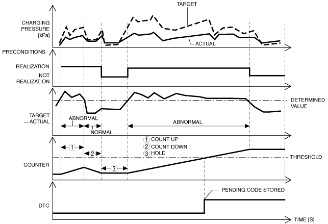
Turbocharger with variable turbine geometry underboost condition |
|
|---|---|---|
|
DETECTION CONDITION
|
Determination conditions
|
• As the result of comparing the actual air charging pressure with the target air charging pressure, the actual air charging pressure is lower or more than specified value compared to the target air charging pressure for a continuous 7 s.
|
|
Preconditions
|
• 2 s have elapsed with all of the following conditions met when DPF regeneration control is stopped during boost control feedback
|
|
|
Drive cycle
|
• 2
|
|
|
Self test type
|
• CMDTC self test
|
|
|
Sensor used
|
• MAP sensor
|
|
|
FAIL-SAFE FUNCTION
|
• Not applicable
|
|
|
VEHICLE STATUS WHEN DTCs ARE OUTPUT
|
• Check engine light is illuminated
|
|
|
POSSIBLE CAUSE
|
• Erratic signal to PCM
• Exhaust gas leakage from exhaust system
• Air suction in intake air system between turbocharger with variable turbine geometry and intake manifold
• Vacuum piping or positive pressure piping of turbocharger actuator malfunction
• Turbocharger solenoid valve malfunction
• Actuator position sensor (turbocharger with variable turbine geometry) malfunction
• Turbocharger actuator malfunction
• Turbocharger with variable turbine geometry malfunction
• PCM malfunction
|
|
System Wiring Diagram
Function Explanation (DTC Detection Outline)
am3zzw00017592
|
Repeatability Verification Procedure
PID Item/Simulation Item Used In Diagnosis
PID/DATA monitor item table
|
Item |
Definition |
Unit |
Condition/Specification |
|---|---|---|---|
|
MAP
|
Manifold absolute pressure input from MAP sensor
|
kPa, Bar, psi
|
• Switch ignition ON (engine off): Approx. 100.37 kPa {1.0235 kgf/cm2, 14.557 psi}
• Idle: Approx. 82 kPa {0.84 kgf/cm2, 12 psi}
|
|
MAP_DSD
|
Manifold absolute pressure desired value
|
kPa, Bar, psi
|
• Displays the manifold absolute pressure desired value
|
Function Inspection Using M-MDS
|
STEP |
INSPECTION |
ACTION |
|
|---|---|---|---|
|
1
|
PURPOSE: RECORD VEHICLE STATUS AT TIME OF DTC DETECTION TO UTILIZE WITH REPEATABILITY VERIFICATION
• Record the FREEZE FRAME DATA/snapshot data on the repair order.
|
—
|
Go to the next step.
|
|
2
|
PURPOSE: VERIFY RELATED SERVICE INFORMATION AVAILABILITY
• Verify related Service Information availability.
• Is any related Service Information available?
|
Yes
|
Perform repair or diagnosis according to the available Service Information.
• If the vehicle is not repaired, go to the next step.
|
|
No
|
Go to the next step.
|
||
|
3
|
PURPOSE: IDENTIFY TRIGGER DTC FOR FREEZE FRAME DATA
• Is the DTC P0299:00 on FREEZE FRAME DATA?
|
Yes
|
Go to the next step.
|
|
No
|
Go to the troubleshooting procedure for DTC on FREEZE FRAME DATA.
(See DTC TABLE [SKYACTIV-D 1.5].)
|
||
|
4
|
PURPOSE: VERIFY IF DIAGNOSTIC RESULT IS AFFECTED BY OTHER RELATED DTCs OCCURRING
• Switch the ignition off, then ON (engine off).
• Perform the Pending Trouble Code Access Procedure and DTC Reading Procedure.
• Is the other PENDING CODE/DTC also present?
|
Yes
|
Go to the applicable DTC inspection.
(See DTC TABLE [SKYACTIV-D 1.5].)
|
|
No
|
Go to the next step.
|
||
|
5
|
PURPOSE: VERIFY IF THERE IS PID ITEM CAUSING DRASTIC CHANGES OF ACCELERATION FLUCTUATION BY INPUT SIGNAL TO PCM
• Access the following PIDs using the M-MDS:
PCM:
• Is there any signal that is far out of specification?
|
Yes
|
Go to the next step.
|
|
No
|
Go to the troubleshooting procedure to perform the procedure from Step 1.
|
||
|
6
|
PURPOSE: VERIFY CONNECTOR CONNECTIONS
• Access the following PIDs using the M-MDS:
PCM:
• When the following parts are shaken, does the PID value include a PID item which has changed?
|
Yes
|
Repair or replace the applicable connector parts.
Go to the troubleshooting procedure to perform the procedure from Step 8.
|
|
No
|
Go to the troubleshooting procedure to perform the procedure from Step 1.
|
||
Troubleshooting Diagnostic Procedure
|
STEP |
INSPECTION |
ACTION |
|
|---|---|---|---|
|
1
|
PURPOSE: INSPECT EXHAUST SYSTEM FOR LEAKAGE
• Visually inspect for exhaust gas leakage from the exhaust system.
• Is there any malfunction?
|
Yes
|
Repair or replace the malfunctioning part according to the inspection results, then go to Step 8.
|
|
No
|
Go to the next step.
|
||
|
2
|
PURPOSE: INSPECT INTAKE AIR SYSTEM FOR AIR SUCTION
• Inspect for air leakage at the following:
• Is there any malfunction?
|
Yes
|
Repair or replace the malfunctioning part according to the inspection results, then go to Step 8.
|
|
No
|
Go to the next step.
|
||
|
3
|
PURPOSE: INSPECT VACUUM PIPING AND POSITIVE PRESSURE PIPING OF TURBOCHARGER ACTUATOR
• Inspect vacuum piping and positive pressure piping of turbocharger actuator.
• Is there hose leakage or damage in the vacuum piping and positive pressure piping?
|
Yes
|
Repair or replace the malfunctioning part according to the inspection results, then go to Step 8.
|
|
No
|
Go to the next step.
|
||
|
4
|
PURPOSE: INSPECT TURBOCHARGER SOLENOID VALVE
• Inspect the turbocharger solenoid valve.
• Is there any malfunction?
|
Yes
|
Replace the turbocharger solenoid valve, then go to Step 8.
|
|
No
|
Go to the next step.
|
||
|
5
|
PURPOSE: INSPECT TURBOCHARGER ACTUATOR
• Inspect the turbocharger actuator.
• Is there any malfunction?
|
Yes
|
Replace the turbocharger with variable turbine geometry, then go to Step 8.
|
|
No
|
Go to the next step.
|
||
|
6
|
PURPOSE: INSPECT ACTUATOR POSITION SENSOR (TURBOCHARGER WITH VARIABLE TURBINE GEOMETRY)
• Inspect the actuator position sensor (turbocharger with variable turbine geometry).
• Is there any malfunction?
|
Yes
|
Replace the turbocharger with variable turbine geometry, then go to Step 8.
|
|
No
|
Go to the next step.
|
||
|
7
|
PURPOSE: INSPECT TURBOCHARGER WITH VARIABLE TURBINE GEOMETRY
• Inspect the turbocharger with variable turbine geometry.
• Is there any malfunction?
|
Yes
|
Replace the turbocharger with variable turbine geometry, then go to the next step.
|
|
No
|
Go to the next step.
|
||
|
8
|
PURPOSE: PERFORM DTC INSPECTION AND VERIFY IF MALFUNCTIONING PART IS PCM
• Always reconnect all disconnected connectors.
• Clear the DTC from the PCM memory using the M-MDS.
• Implement the repeatability verification procedure.
• Perform the Pending Trouble Code Access Procedure.
• Is the PENDING CODE for this DTC present?
|
Yes
|
Repeat the inspection from Step 1.
• If the malfunction recurs, replace the PCM.
Go to the next step.
|
|
No
|
Go to the next step.
|
||
|
9
|
PURPOSE: VERIFY AFTER REPAIR PROCEDURE
• Perform the “AFTER REPAIR PROCEDURE”.
• Are any DTCs present?
|
Yes
|
Go to the applicable DTC inspection.
(See DTC TABLE [SKYACTIV-D 1.5].)
|
|
No
|
DTC troubleshooting completed.
|
||