 |
am3zzw00014433
DTC P0A12:00 [SKYACTIV-D 2.2]
id0102s4569000
Details On DTCs
|
DESCRIPTION |
DC-DC converter (i-ELOOP): low input/output |
|
|---|---|---|
|
DETECTION CONDITION
|
Determination conditions
|
• Any one of the following conditions is met:
|
|
Preconditions
|
• Not applicable
|
|
|
Drive cycle
|
• 1
|
|
|
Self test type
|
• CMDTC self test
|
|
|
Sensor used
|
• Not applicable
|
|
|
FAIL-SAFE FUNCTION
|
• Inhibits engine-stop by operating the i-stop function.
• Depending on the type of malfunction, any of the following controls may be implemented.
|
|
|
VEHICLE STATUS WHEN DTCs ARE OUTPUT
|
• Flashes i-stop warning light (amber).
• A warning message is displayed on the center display. (Type A instrument cluster)
• A warning message is displayed on the LCD in the instrument cluster. (Type B instrument cluster)
• Illuminates charging system warning light.
• If the vehicle continues to be driven while the DTC is detected the battery will be depleted.
• The following vehicle conditions differ depending on the type of malfunction:
|
|
|
POSSIBLE CAUSE
|
• Connector or terminal malfunction of the following parts:
• Malfunction in the following fuses:
• Short to ground in wiring harness between the following terminals:
• Open circuit in wiring harness between the following terminals:
• High-power load, non-genuine part installed to line connected to DC-DC converter (i-ELOOP) terminal 2A (DTC P0A94:00 may be detected simultaneously)
• DC-DC converter (i-ELOOP) malfunction
• PCM malfunction
|
|
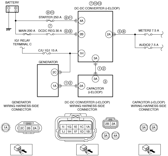
System Wiring Diagram
am3zzw00014433
|
Function Explanation (DTC Detection Outline)
Repeatability Verification Procedure
PID Item/Simulation Item Used In Diagnosis
Function Inspection Using M-MDS
|
STEP |
INSPECTION |
RESULTS |
ACTION |
|---|---|---|---|
|
1
|
PURPOSE: VERIFY RELATED SERVICE INFORMATION AVAILABILITY
• Verify related Service Information availability.
• Is any related Service Information available?
|
Yes
|
Perform repair or diagnosis according to the available Service Information.
• If the vehicle is not repaired, go to the next step.
|
|
No
|
Go to the next step.
|
||
|
2
|
PURPOSE: VERIFY IF POWER SUPPLY IS AFFECTED BY DTC RELATED TO DC-DC CONVERTER (i-ELOOP)
• Switch the ignition off, then ON (engine off).
• Perform the DC-DC converter (i-ELOOP) DTC inspection using the M-MDS.
(See DTC INSPECTION [i-ELOOP].)
• Is the PENDING CODE/DTC U3000:49 also present?
|
Yes
|
Go to the applicable PENDING CODE or DTC inspection.
(See DTC U3000:49 [i-ELOOP].)
Go to the next step.
|
|
No
|
Go to the next step.
|
||
|
3
|
PURPOSE: VERIFY IF POWER SUPPLY IS AFFECTED BY DTC RELATED TO DC-DC CONVERTER (i-ELOOP)
• Perform the DC-DC converter (i-ELOOP) DTC inspection using the M-MDS.
(See DTC INSPECTION [i-ELOOP].)
• Is the PENDING CODE/DTC P1628:11 also present?
|
Yes
|
Go to the applicable PENDING CODE or DTC inspection.
(See DTC P1628:11 [i-ELOOP].)
Go to the next step.
|
|
No
|
Go to the next step.
|
||
|
4
|
PURPOSE: VERIFY IF POWER SUPPLY IS AFFECTED BY DTC RELATED TO PCM
• Perform the Pending Trouble Code Access Procedure and DTC Reading Procedure.
• Is the PENDING CODE/DTC P0A94:00 also present?
|
Yes
|
Go to Step 6.
|
|
No
|
Go to the next step.
|
||
|
5
|
PURPOSE: DETERMINE IF MALFUNCTION CAUSED BY DC-DC CONVERTER (i-ELOOP)
• Start the engine.
• Is a message related to i-ELOOP displayed in the display?
|
Yes
|
Go to the troubleshooting procedure to perform the procedure from Step 1.
|
|
No
|
Go to the next step.
|
||
|
6
|
PURPOSE: DETERMINE LOCATION OF MALFUNCTION OCCURRENCE FROM BLOWN DCDC REG 30 A FUSE
• Switch the ignition off.
• Inspect the DCDC REG 30 A fuse.
• Is the DCDC REG 30 A fuse blown?
|
Yes
|
Go to the troubleshooting procedure to perform the procedure from Step 4.
|
|
No
|
Go to the next step.
|
||
|
7
|
PURPOSE: DETERMINE LOCATION OF MALFUNCTION FROM OPERATION CONDITION OF VEHICLE ELECTRICAL DEVICES
• Turn on the audio unit/car navigation unit power.
• Can the power be turned on?
|
Yes
|
Go to the next step.
|
|
No
|
Go to the troubleshooting procedure to perform the procedure from Step 8.
|
||
|
8
|
PURPOSE: DETERMINE LOCATION OF MALFUNCTION OCCURRENCE FROM BLOWN STARTER 250 A FUSE
• Switch the ignition off.
• Inspect the STARTER 250 A fuse.
• Is the STARTER 250 A fuse blown?
|
Yes
|
Go to the troubleshooting procedure to perform the procedure from Step 9.
|
|
No
|
Go to the troubleshooting procedure to perform the procedure from Step 11.
|
Troubleshooting Diagnostic Procedure
|
STEP |
INSPECTION |
RESULTS |
ACTION |
|---|---|---|---|
|
1
|
PURPOSE: VERIFY IF SHORT TO GROUND IN EACH WIRING HARNESS AFFECTS DIAGNOSTIC RESULTS
• Switch the ignition off.
• Remove the service plug.
• Disconnect the connector of the following parts.
• Inspect for continuity between the following terminals (wiring harness-side) and body ground:
• Is there continuity?
|
Yes
|
Refer to the wiring diagram and verify whether or not there is a common connector between the following terminals:
• Capacitor (i-ELOOP) terminal 2A—Generator terminal 1A
• Capacitor (i-ELOOP) terminal 3A—DC-DC converter (i-ELOOP) terminal 3A
If there is a common connector:
• Determine the malfunctioning part by inspecting the common connector and the terminal for corrosion, damage, or pin disconnection, and the common wiring harness for a short to ground.
• Repair or replace the malfunctioning part.
If there is no common connector:
• Repair or replace the wiring harness which has a short to ground.
Go to Step 3.
|
|
No
|
Go to the next step.
|
||
|
2
|
PURPOSE: VERIFY IF OPEN CIRCUIT IN EACH WIRING HARNESS AFFECTS DIAGNOSTIC RESULTS
• Verify that the generator, capacitor (i-ELOOP), and DC-DC converter (i-ELOOP) connectors are disconnected.
• Inspect for continuity between the following terminals (wiring harness-side):
• Is there continuity?
|
Yes
|
Go to Step 11.
|
|
No
|
Refer to the wiring diagram and verify whether or not there is a common connector between the following terminals:
• Capacitor (i-ELOOP) terminal 2A—Generator terminal 1A
• Capacitor (i-ELOOP) terminal 3A—DC-DC converter (i-ELOOP) terminal 3A
If there is a common connector:
• Determine the malfunctioning part by inspecting the common connector and the terminal for corrosion, damage, or pin disconnection, and the common wiring harness for an open circuit.
• Repair or replace the malfunctioning part.
If there is no common connector:
• Repair or replace the wiring harness which has an open circuit.
Go to the next step.
|
||
|
3
|
PURPOSE: VERIFICATION OF VEHICLE REPAIR COMPLETION
• Always reconnect all disconnected connectors.
• Reinstall the service plug.
• Start the engine.
• Is the master warning light turned on approx. 3 min after a message related to i-ELOOP is displayed in the display?
|
Yes
|
Replace the capacitor (i-ELOOP).
Go to Step 14.
|
|
No
|
Go to Step 14.
|
||
|
4
|
PURPOSE: VERIFY IF INSTALLATION OF NON-GENUINE PART IS CAUSING MALFUNCTION
• Verify if non-genuine part in which electric load occurs is installed.
• Is a non-genuine electrical part in which electric load occurs installed?
|
Yes
|
Explain to the customer that the vehicle is normal and that the i-ELOOP does not operate because of the vehicle's electrical load.
Remove the non-genuine part in consultation with the customer.
Go to Step 14.
|
|
No
|
Go to the next step.
|
||
|
5
|
PURPOSE: VERIFY IF SHORT TO GROUND IN EACH WIRING HARNESS AFFECTS DIAGNOSTIC RESULTS
• Switch the ignition off.
• Remove the service plug.
• Disconnect the DC-DC converter (i-ELOOP) connector.
• Inspect for continuity between the following terminals (wiring harness-side) and body ground:
• Is there continuity?
|
Yes
|
Refer to the wiring diagram and verify whether or not there is a common connector between the following terminals:
• DC-DC converter (i-ELOOP) terminal 2A—AUDIO2 7.5 A
• DC-DC converter (i-ELOOP) terminal 2A—METER2 7.5 A
If there is a common connector:
• Determine the malfunctioning part by inspecting the common connector and the terminal for corrosion, damage, or pin disconnection, and the common wiring harness for a short to ground.
• Repair or replace the malfunctioning part.
If there is no common connector:
• Repair or replace the wiring harness which has a short to ground.
Replace the DCDC REG 30 A fuse.
Go to Step 14.
|
|
No
|
Go to the next step.
|
||
|
6
|
PURPOSE: VERIFY IF SHORT TO GROUND IN EACH WIRING HARNESS AFFECTS DIAGNOSTIC RESULTS
• Verify that the DC-DC converter (i-ELOOP) connector is disconnected.
• Inspect for continuity between the following terminals (wiring harness-side) and body ground:
• Is there continuity?
|
Yes
|
Refer to the wiring diagram and verify whether or not there is a common connector between the following terminals:
• Battery positive terminal—DC-DC converter (i-ELOOP) terminal 2B
If there is a common connector:
• Determine the malfunctioning part by inspecting the common connector and the terminal for corrosion, damage, or pin disconnection, and the common wiring harness for a short to ground.
• Repair or replace the malfunctioning part.
If there is no common connector:
• Repair or replace the wiring harness which has a short to ground.
Replace the DCDC REG 30 A fuse.
Go to Step 14.
|
|
No
|
Go to the next step.
|
||
|
7
|
PURPOSE: VERIFICATION OF VEHICLE REPAIR COMPLETION
• Repelace the DCDC REG 30 A fuse.
• Always reconnect all disconnected connectors.
• Reinstall the service plug.
• Start the engine.
• Inspect the DCDC REG 30 A fuse.
• Is the DCDC REG 30 A fuse blown?
|
Yes
|
Replace the DCDC REG 30 A fuse and DC-DC converter (i-ELOOP).
Go to Step 14.
|
|
No
|
Go to Step 14.
|
||
|
8
|
PURPOSE: VERIFY IF OPEN CIRCUIT IN EACH WIRING HARNESS AFFECTS DIAGNOSTIC RESULTS
• Switch the ignition off.
• Remove the service plug.
• Disconnect the DC-DC converter (i-ELOOP) connector.
• Inspect for continuity between the following terminals (wiring harness-side):
• Is there continuity?
|
Yes
|
Go to the "Function Inspection Using M-MDS“ to perform the procedure from Step 7.
|
|
No
|
Refer to the wiring diagram and verify whether or not there is a common connector between the following terminals:
• DC-DC converter (i-ELOOP) terminal 2A—AUDIO2 7.5 A
• DC-DC converter (i-ELOOP) terminal 2A—METER2 7.5 A
• Battery positive terminal—DC-DC converter (i-ELOOP) terminal 2B
If there is a common connector:
• Determine the malfunctioning part by inspecting the common connector and the terminal for corrosion, damage, or pin disconnection, and the common wiring harness for an open circuit.
• Repair or replace the malfunctioning part.
If there is no common connector:
• Repair or replace the wiring harness which has an open circuit.
Go to Step 14.
|
||
|
9
|
PURPOSE: VERIFY IF SHORT TO GROUND IN EACH WIRING HARNESS AFFECTS DIAGNOSTIC RESULTS
• Switch the ignition off.
• Remove the service plug.
• Disconnect the DC-DC converter (i-ELOOP) connector.
• Inspect for continuity between the following terminals (wiring harness-side) and body ground:
• Is there continuity?
|
Yes
|
Refer to the wiring diagram and verify whether or not there is a common connector between the following terminals:
• Battery positive terminal—DC-DC converter (i-ELOOP) terminal 4A
If there is a common connector:
• Determine the malfunctioning part by inspecting the common connector and the terminal for corrosion, damage, or pin disconnection, and the common wiring harness for a short to ground.
• Repair or replace the malfunctioning part.
If there is no common connector:
• Repair or replace the wiring harness which has a short to ground.
Replace the STARTER 250 A fuse.
Go to Step 14.
|
|
No
|
Go to the next step.
|
||
|
10
|
PURPOSE: VERIFICATION OF VEHICLE REPAIR COMPLETION
• Repelace the STARTER 250 A fuse.
• Always reconnect all disconnected connectors.
• Reinstall the service plug.
• Start the engine.
• Inspect the STARTER 250 A fuse.
• Is the STARTER 250 A fuse blown?
|
Yes
|
Replace the STARTER 250 A fuse and DC-DC converter (i-ELOOP).
Go to Step 14.
|
|
No
|
Go to Step 14.
|
||
|
11
|
PURPOSE: VERIFY IF OPEN CIRCUIT IN EACH WIRING HARNESS AFFECTS DIAGNOSTIC RESULTS
• Switch the ignition off.
• Remove the service plug.
• Disconnect the DC-DC converter (i-ELOOP) connector.
• Inspect for continuity between the following terminals (wiring harness-side):
• Is there continuity?
|
Yes
|
Go to the next step.
|
|
No
|
Refer to the wiring diagram and verify whether or not there is a common connector between the following terminals:
• Battery positive terminal—DC-DC converter (i-ELOOP) terminal 4A
If there is a common connector:
• Determine the malfunctioning part by inspecting the common connector and the terminal for corrosion, damage, or pin disconnection, and the common wiring harness for an open circuit.
• Repair or replace the malfunctioning part.
If there is no common connector:
• Repair or replace the wiring harness which has an open circuit.
Go to the next step.
|
||
|
12
|
PURPOSE: VERIFY IF MALFUNCTION OCCURRING IS CAUSED BY WIRING HARNESS/CONNECTOR LOSS
• Have all the wiring harnesses/connectors which can be considered the cause of DTC P0A12:00 been inspected?
|
Yes
|
Go to the next step.
|
|
No
|
Inspect all the related wiring harnesses/connectors.
If there is a malfunction
• Repair or replace the connector and/or terminals, then go to Step 14.
If there is no malfunction
• Go to the next step.
|
||
|
13
|
PURPOSE: VERIFY DC-DC CONVERTER (i-ELOOP) REPLACEMENT RECORD
• Is the DC-DC converter (i-ELOOP) being replaced within the troubleshooting diagnostic procedure this time?
|
Yes
|
Replace the PCM.
Go to the next step.
|
|
No
|
Replace the DC-DC converter (i-ELOOP).
Go to the next step.
|
||
|
14
|
PURPOSE: VERIFICATION OF VEHICLE REPAIR COMPLETION
• Always reconnect all disconnected connectors.
• Reinstall the service plug.
• Clear the DTC from the PCM memory using the M-MDS.
• Implement the repeatability verification procedure.
• Perform the DTC Reading Procedure.
• Is the same DTC present?
|
Yes
|
Repeat the inspection from Step 12.
|
|
No
|
Go to the next step.
|
||
|
15
|
PURPOSE: VERIFY IF THERE IS ANY OTHER MALFUNCTION
• Is any other DTC or pending code stored?
|
Yes
|
Go to the applicable DTC inspection.
(See DTC TABLE [SKYACTIV-D 2.2].)
|
|
No
|
DTC troubleshooting completed.
|