 |
am3uuw00011035
REAR CROSSMEMBER REMOVAL/INSTALLATION
id021400801000
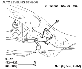
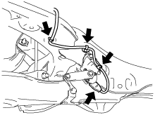
1. Disconnect the wiring harness clips and connector installed to the rear crossmember. (With auto leveling sensor)
am3uuw00011035
|
2. Remove the auto leveling sensor. (With auto leveling sensor) (See AUTO LEVELING SENSOR REMOVAL/INSTALLATION.)
am3uuw00011342
|
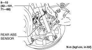
3. Disconnect the rear ABS wheel-speed sensor wiring harness installed to the hub support and set it aside. (See REAR ABS WHEEL-SPEED SENSOR REMOVAL/INSTALLATION.)
am3uuw00011339
|
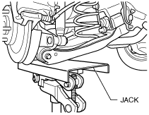
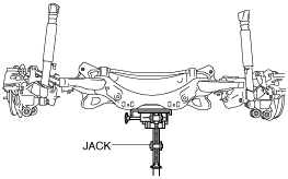
4. Jack up the vehicle to the unloaded condition, and support the rear trailing link component using a jack.
ac5wzw00002868
|
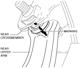
5. Align the rear crossmember component and rear upper arm and mark them.
ac5uuw00000186
|
6. Remove the presilencer. (MZR 1.6) (See EXHAUST SYSTEM REMOVAL/INSTALLATION [MZR 1.6].)
7. Remove the TWC. (SKYACTIV-G 1.5, SKYACTIV-G 2.0, SKYACTIV-G 2.5) (See EXHAUST SYSTEM REMOVAL/INSTALLATION [SKYACTIV-G 1.5, SKYACTIV-G 2.0, SKYACTIV-G 2.5].)
8. Remove the middle pipe. (SKYACTIV-D 1.5, SKYACTIV-D 2.2) (See EXHAUST SYSTEM REMOVAL/INSTALLATION [SKYACTIV-D 1.5].) (See EXHAUST SYSTEM REMOVAL/INSTALLATION [SKYACTIV-D 2.2].)
9. Remove the rear lateral link. (See REAR LATERAL LINK REMOVAL/INSTALLATION.)
10. Remove the rear coil spring. (See REAR COIL SPRING REMOVAL/INSTALLATION.)
11. Remove the rear lower arm. (See REAR LOWER ARM REMOVAL/INSTALLATION.)
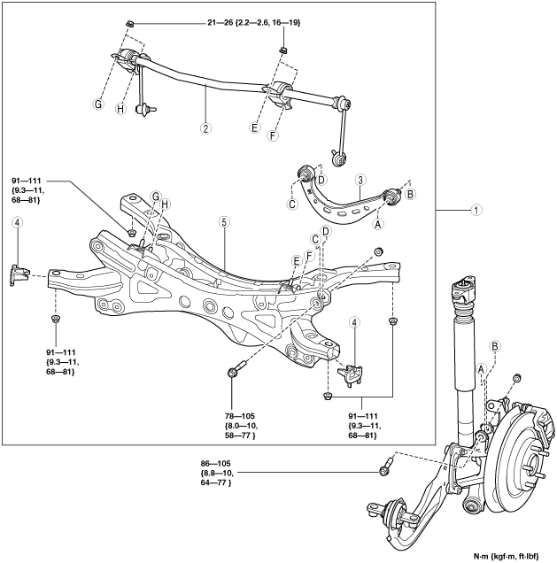
12. Remove in the order indicated in the table.
13. Install in the reverse order of removal.
14. Inspect the wheel alignment and adjust it if necessary. (See REAR WHEEL ALIGNMENT.)
am3uuw00011047
|
|
1
|
Rear crossmember component
|
|
2
|
Rear stabilizer component
|
|
3
|
Rear upper arm
|
|
4
|
Rear crossmember mudguard
|
|
5
|
Rear crossmember
|
Rear Crossmember Component Removal Note
1. Support the rear crossmember with the jack and remove the nuts
am3uuw00011037
|
2. Remove the rear crossmember component.
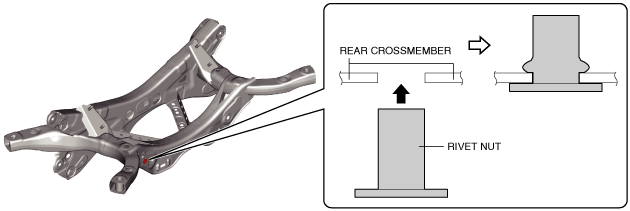
Rear Crossmember Installation Note
1. When replacing the rear crossmember, install the rivet nut using a rivet nut tool.
am3zzw00018021
|
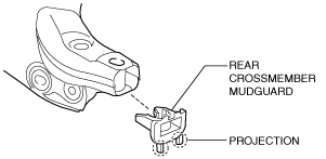
Rear Crossmember Mudguard Installation Note
1. Install with the rear crossmember mudguard projection pointed downward.
am3uuw00012099
|
Rear Crossmember Component Installation Note
1. Support the rear crossmember component and install the rear crossmember.
am3uuw00011037
|