 |
am3uuw00012069
DIAGNOSTIC ASSIST FUNCTION [CONNECTIVITY MASTER UNIT]
id0902n7039300
Activation Procedure
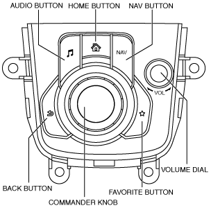
Using commander switch
1. Switch the ignition to ACC or ON (engine off or on).
2. Press the following buttons simultaneously for 2 s or more.
am3uuw00012069
|
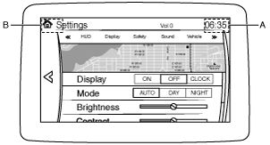
Using center display
1. Switch the ignition to ACC or ON (engine off or on).
2. Display the display setting screen in the center display.
3. Operate the center display in the following order.
am3uuw00012499
|
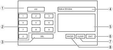
Diagnostic Assist Code Input Procedure
Diagnostic assist code input screen
am3uuw00011843
|
|
No. |
Name |
Content/function |
|---|---|---|
|
1
|
Diagnostic assist code display screen
|
Displays the diagnostic assist code.
|
|
2
|
Diagnostic assist code input switch
|
Inputs the diagnostic assist code.
|
|
3
|
DEL switch
|
Clears the diagnostic assist code.
|
|
4
|
Diagnostic content display screen
|
Displays the diagnostic content.
|
|
5
|
Diagnostic results display screen
|
Displays the diagnostic results.
|
|
6
|
EXIT switch*1/END switch*2
|
Cancels the diagnostic assist function./Stops the diagnostic assist function being performed.
|
|
7
|
CLEAR switch
|
Clears the diagnostic result display.
|
|
8
|
ENTER switch
|
Transfers to the diagnostic assist function.
|
Using commander switch
1. Input the diagnostic assist code by rotating the commander knob.
am3uuw00012069
|
2. Press the commander knob.
3. Perform the inspection according to the diagnostic assist code list. (See Diagnostic Assist Code List.)
Using center display
1. Input the diagnostic assist code by pressing the “Diagnostic assist code input switch”.
2. Press “ENTER”.
3. Perform the inspection according to the diagnostic assist code list. (See Diagnostic Assist Code List.)
[- REJECTED] is displayed
1. Switch the ignition off.
2. Launch the diagnostic assist function. (See Activation Procedure.)
3. Input the diagnostic assist code. (See Diagnostic Assist Code Input Procedure.)
4. Verify that [- REJECTED] is not displayed.
Ending Procedure
1. While the inspection is being performed, press “END” to return to the diagnostic assist code input screen.
2. Cancel the diagnostic assist function by pressing “EXIT”.
Diagnostic Assist Code List
|
No. |
Center display (diagnostic content) |
Content/function |
Reference |
|---|---|---|---|
|
01
|
CD Test
|
CD player inspection
|
|
|
02
|
Clear DTC
|
DTC clearing
|
|
|
03
|
Read AVC DTC
|
Inspection of all DTCs related to module
|
|
|
04
|
Read CMU DTC
|
DTC inspection for connectivity master unit (CMU)
|
|
|
05
|
Read TAU DTC
|
DTC inspection for tuner and amplifier unit (TAU)
|
DTC inspection
|
|
06
|
Read CD DTC
|
DTC inspection for CD player
|
DTC inspection
|
|
07
|
Read DTV DTC
|
Does not operate due to unavailability of applicable DTC.
|
|
|
08
|
Software Reset AVC
|
Do not operate because item is for manufacturer use.
|
|
|
09
|
Software Version Display (CD)
|
Software version verification
|
|
|
10
|
Part Number Readout CD/DVD
|
Part number verification
|
|
|
25
|
Antenna Continuity Status
|
Antenna control output condition inspection
|
|
|
26
|
DTV TEST ON
|
Do not operate because item is for manufacturer use.
|
|
|
27
|
DTV TEST OFF
|
Do not operate because item is for manufacturer use.
|
|
|
53
|
Software Version Display (CMU)
|
Software version verification
|
|
|
57
|
Software Version Display (VIP)
|
Software version verification
|
|
|
58
|
Vehicle Info
|
Configuration information verification
|
|
|
59
|
CMU Serial Number Readout
|
Individual number verification
|
|
|
61
|
Vehicle Signal (Unit Status)
|
Vehicle signal verification
|
|
|
65
|
Commander and Switch Check
|
Switch inspection
|
|
|
68
|
Software version display (TFT Display)
|
Software version verification
|
|
|
69
|
Software version display (Touch Panel)
|
Software version verification
|
|
|
70
|
Display Check
|
Display/touch panel inspection
|
|
|
72
|
GPS Data
|
GPS information verification
|
|
|
84
|
Maker code Display TAU
|
Manufacturer verification
|
|
|
85
|
Part Number Readout TAU
|
Part number verification
|
|
|
86
|
Radio Test Mode AM (Main)
|
Do not operate because item is for manufacturer use.
|
|
|
87
|
HD Certification (Main Tuner)
|
Do not operate because item is for manufacturer use.
|
|
|
88
|
HD Certification (Sub Tuner)
|
Do not operate because item is for manufacturer use.
|
|
|
89
|
XM Certification
|
Do not operate because item is for manufacturer use.
|
|
|
90
|
AM Reception Sensitivity Level Test
|
Radio reception condition inspection
|
|
|
91
|
Radio Test Mode (Main)
|
Do not operate because item is for manufacturer use.
|
|
|
92
|
Radio Test Mode (Sub)
|
Do not operate because item is for manufacturer use.
|
|
|
93
|
Software Version Display (TAU)
|
Software version verification
|
|
|
94
|
Speaker Cyclic Test
|
Speaker Inspection
|
|
|
95
|
Vehicle Info Display (TAU)
|
Do not operate because item is for manufacturer use.
|
|
|
96
|
XM Serial Number
|
Do not operate because it is displayed, but, not function.
|
|
|
97
|
Radio Electric Field Strength (AM)
|
Do not operate because item is for manufacturer use.
|
|
|
98
|
Radio Electric Field Strength (FM)
|
Do not operate because item is for manufacturer use.
|
|
|
99
|
Software Update
|
Do not operate because item is for manufacturer use.
|
|
Diagnostic assist code “01” CD player inspection
1. Input diagnostic assist code “01” according to the diagnostic assist code input procedure. (See Diagnostic Assist Code Input Procedure.)
2. After inputting the diagnostic assist code, insert the CD into the CD player within 10 s.
|
Inspection |
Display of center display (Diagnostic result) |
Content |
Action |
|---|---|---|---|
|
• Launch the CD player inspection mode.
• Verify the inspection result.
|
CD OK
|
CD is normal.
• After inspection, a malfunction is not detected.
|
• The CD player is operating normally.
|
|
CD Mechanical Linkage Failure
|
CD read failure
• Disc is not loaded normally due to a malfunction (damage or deformation) on disc or CD player malfunction.
|
• Verify that CD is not damaged or deformed.
If there is a malfunction:
If there is no malfunction:
|
|
|
CD Signal Plausibility Failure
|
CD data format error
• Disc is loaded, but system detects disc which CD player cannot read.
|
• Replace with a compatible CD.
|
3. Cancel the diagnostic assist function according to the ending procedure. (See Ending Procedure.)
Diagnostic Assist Code “02” DTC Clear
1. Input diagnostic assist code “02” according to the diagnostic assist code input procedure. (See Diagnostic Assist Code Input Procedure.)
2. Verify that all DTCs are cleared.
3. Cancel the diagnostic assist function according to the ending procedure. (See Ending Procedure.)
Diagnostic Assist Code “03/04/05/06” DTC Inspection
1. Verify the module to be inspected for DTCs referring to the chart, then input the diagnostic assist code according to the diagnostic assist code input procedure. (See Diagnostic Assist Code Input Procedure.)
|
Diagnostic assist code |
Modules which can be verified for DTC |
||
|---|---|---|---|
|
Connectivity master unit (CMU) |
Tuner and amplifier unit (TAU) |
CD player |
|
|
03*1
|
×
|
×
|
×
|
|
04
|
×
|
—
|
—
|
|
05
|
—
|
×
|
—
|
|
06
|
—
|
—
|
×
|
2. If a DTC is displayed, repair the malfunctioning location according to the applicable DTC troubleshooting. (See DTC TABLE [CONNECTIVITY MASTER UNIT].)
3. Cancel the diagnostic assist function according to the ending procedure. (See Ending Procedure.)
Diagnostic Assist Code “09/53/57/68/69/93” Software Version Verification
1. Verify the module to be inspected for the software version referring to the chart, then input the diagnostic assist code according to the diagnostic assist code input procedure. (See Diagnostic Assist Code Input Procedure.)
|
Diagnostic assist code |
Software version to be verified |
|---|---|
|
09
|
CD player
|
|
53
|
Connectivity master unit (CMU) (overall entertainment system)
|
|
57
|
Connectivity master unit (CMU) (overall communication system between vehicle)
|
|
68
|
Center display (TFT LCD screen control system)
|
|
69
|
Center display (Touch panel control system)
|
|
93
|
Tuner and amplifier unit (TAU)
|
2. Cancel the diagnostic assist function according to the ending procedure. (See Ending Procedure.)
Diagnostic Assist Code “10/85” Part Number Verification
1. Verify the module to be inspected for the part number referring to the chart, then input the diagnostic assist code according to the diagnostic assist code input procedure. (See Diagnostic Assist Code Input Procedure.)
|
Diagnostic assist code |
Module to be verified for part number |
|---|---|
|
10
|
CD player
|
|
85
|
Tuner and amplifier unit (TAU)
|
2. Verify the part number.
3. Cancel the diagnostic assist function according to the ending procedure. (See Ending Procedure.)
Diagnostic Assist Code “25” Antenna Control Output Condition Inspection
1. Input diagnostic assist code “25” according to the diagnostic assist code input procedure. (See Diagnostic Assist Code Input Procedure.)
2. Inspect the malfunctioning location according to the following table:
|
Inspection |
Display of center display (Diagnostic result) |
Action |
|
|---|---|---|---|
|
• Launch the antenna control output condition inspection mode.
|
ANT-ON
|
Good sound quality
|
System is normal.
|
|
Bad sound quality
|
Inspect the glass antenna, antenna amplifier (4SD)/center roof antenna (5HB), and antenna feeder.
(See GLASS ANTENNA INSPECTION.)
• If the glass antenna, antenna amplifier (4SD)/center roof antenna (5HB), or antenna feeder is malfunctioning:
• If the glass antenna, antenna amplifier (4SD)/center roof antenna (5HB), and antenna feeder are normal:
|
||
|
ANT-OFF
|
Output cannot be verified
|
Replace the tuner and amp unit (TAU).
|
|
3. Cancel the diagnostic assist function according to the ending procedure. (See Ending Procedure.)
Diagnostic Assist Code “58” Configuration Information Verification
1. Input diagnostic assist code “58” according to the diagnostic assist code input procedure. (See Diagnostic Assist Code Input Procedure.)
2. Verify the configuration information.
|
Display of center display |
Content |
|---|---|
|
Destination
|
Destination information
|
|
CMU Types
|
Recognition condition whether connectivity master unit (CMU) is equipped or not
|
3. Cancel the diagnostic assist function according to the ending procedure. (See Ending Procedure.)
Diagnostic Assist Code “59” Individual Number Verification
1. Input diagnostic assist code “59” according to the diagnostic assist code input procedure. (See Diagnostic Assist Code Input Procedure.)
2. Verify the individual number of the connectivity master unit (CMU).
3. Cancel the diagnostic assist function according to the ending procedure. (See Ending Procedure.)
Diagnostic Assist Code “61” Vehicle Signal Verification
1. Input diagnostic assist code “61” according to the diagnostic assist code input procedure. (See Diagnostic Assist Code Input Procedure.)
2. Verify the vehicle signal.
|
Display of center display (Diagnostic result) |
Content |
|---|---|
|
ST-SW
|
Steering switch signal input condition
|
|
Commander
|
Commander switch signal input condition
|
|
GPS
|
GPS antenna signal input condition
|
|
Microphone
|
Voice recognition microphone signal input condition
|
|
HUB1
|
HUB1 signal input condition
|
|
HUB2
|
HUB2 signal input condition
|
|
RS-485
|
RS-485 signal input condition
|
|
NAVI (SD)
|
SD card insertion condition
|
|
CD/DVD
|
DVD/CD equipment recognition condition
|
|
DTV
|
TV tuner unit equipment recognition condition
|
3. Cancel the diagnostic assist function according to the ending procedure. (See Ending Procedure.)
Diagnostic Assist Code “65” Switch Inspection
1. Input diagnostic assist code “65” according to the diagnostic assist code input procedure. (See Diagnostic Assist Code Input Procedure.)
2. Perform the steering switch inspection or commander switch inspection.
Steering switch inspection
|
Inspection |
Display of center display (Diagnostic result) |
Action |
|
|---|---|---|---|
|
• Launch the switch inspection mode.
• Operate each switch of the steering switch.
• Does the display in the center display correspond to each operation?
|
• ST-SW Talk Button Pressed: TALK switch is pressed
• ST-SW Talk Button Released: TALK switch is released
• ST-SW Pick-Up Button Pressed: Pick-Up switch is pressed
• ST-SW Pick-Up Button Released: Pick-Up switch is released
• ST-SW Hang-Up Button Pressed: Hang-Up switch is pressed
• ST-SW Hang-Up Button Released: Hang-Up switch is released
• ST-SW Volume + Button Pressed: VOLUME (+) switch is pressed
• ST-SW Volume + Button Released: VOLUME (+) switch is released
• ST-SW Volume - Button Pressed: VOLUME (-) switch is pressed
• ST-SW Volume - Button Released: VOLUME (-) switch is released
• ST-SW Seek + Button Pressed: Seek (+) switch is pressed
• ST-SW Seek + Button Released: SEEK (+) switch is released
• ST-SW Seek - Button Pressed: Seek (-) switch is pressed
• ST-SW Seek - Button Released: Seek (-) switch is released
|
Yes
|
The steering switch is normal.
|
|
No
|
Inspect the steering switch.
(See STEERING SWITCH INSPECTION.)
• If there is a malfunction:
• If the steering switch is normal:
|
||
Commander switch inspection
|
Inspection |
Display of center display (Diagnostic result) |
Action |
|
|---|---|---|---|
|
• Launch the switch inspection mode.
• Operate each button and knob of the commander switch.
• Does the display in the center display correspond to each operation?
|
• Home Button Pressed: HOME button is pressed
• Home Button Released: HOME button is released
• Navi Button Pressed: NAV button is pressed
• Navi Button Released: NAV button is released
• Audio Button Pressed: AUDIO button is pressed
• Audio Button Released: AUDIO button is released
• Favorites Button Pressed: FAVORITE button is pressed
• Favorites Button Released: FAVORITE button is released
• Back Button Pressed: BACK button is pressed
• Back Button Released: BACK button is released
• Commander Pushed In: Commander knob is pressed
• Commander Released: Commander knob is released
• Tilt Up Pressed: Commander knob is tilted up
• Tilt Up Released: Commander knob is released from tilted up condition
• Tilt Right Pressed: Commander knob is tilted to the right
• Tilt Right Released: Commander knob is released from tilted right condition
• Tilt Down Pressed: Commander knob is tilted down
• Tilt Down Released: Commander knob is released from tilted down condition
• Tilt Left Pressed: Commander knob is tilted to the left
• Tilt Left Released: Commander knob is released from tilted left condition
• Commander Turned Clockwise: Commander knob is turned clockwise
• Commander Turned Counter Clockwise: Commander knob is turned counterclockwise
• Volume Knob Pushed In: Volume dial is pressed
• Volume Knob Released: Volume dial is released
• Volume Knob Turned Clockwise: Volume dial is turned clockwise
• Volume Knob Turned Counter Clockwise: Volume dial is turned counterclockwise
|
Yes
|
Commander switch is normal.
|
|
No
|
Replace the commander switch.
|
||
3. Cancel the diagnostic assist function according to the ending procedure. (See Ending Procedure.)
Diagnostic Assist Code “70” Display/Touch Panel Inspection
1. Input diagnostic assist code “70” according to the diagnostic assist code input procedure. (See Diagnostic Assist Code Input Procedure.)
|
Inspection |
Display of center display (Diagnostic result) |
Action |
|
|---|---|---|---|
|
• Launch the display/touch panel inspection mode.
• Verify the center display.
• Does the center display display normally?
|
If normal, [+] cursor is displayed centering around the touched area, and at the same time, the display switches in the following order.
1. Unicolor screen in the following colors
2. Horizontal-striped screen in black and the following colors
3. Vertical-striped screen in black and the following colors
4. Checkered screen in black and the following colors
5. Returns to 1.
|
Yes
|
Center display is normal.
|
|
No
|
Replace the center display.
|
||
2. Continuously touch the same location for 10 s or more.
Diagnostic Assist Code “72” GPS Information Verification
1. Input diagnostic assist code “72” according to the diagnostic assist code input procedure. (See Diagnostic Assist Code Input Procedure.)
2. Verify the GPS information.
|
Display of center display (Diagnostic result) |
Content |
|---|---|
|
Longitude (X)
|
Degree of longitude in GPS information of the current location
|
|
Latitude (Y)
|
Degree of latitude in GPS information of the current location
|
|
Absolute Time (Z)
|
Date and time information (GMT)
|
|
Number of Satellites
|
Number of satellites being received
|
3. Cancel the diagnostic assist function according to the ending procedure. (See Ending Procedure.)
Diagnostic Assist Code “84” Manufacturer Name Verification
1. Input diagnostic assist code “84” according to the diagnostic assist code input procedure. (See Diagnostic Assist Code Input Procedure.)
2. Verify the manufacturer name.
3. Cancel the diagnostic assist function according to the ending procedure. (See Ending Procedure.)
Diagnostic Assist Code “90” Radio Reception Condition Inspection
1. Tune in the radio.
2. Input diagnostic assist code “90” according to the diagnostic assist code input procedure. (See Diagnostic Assist Code Input Procedure.)
3. Inspect the malfunctioning location according to the following table:
|
Inspection |
Display of center display (Diagnostic result) |
Action |
|---|---|---|
|
• Start the radio reception condition inspection mode.
• Select frequency (radio station) by operating the commander knob.
• Verify the inspection result.
|
TAU AM Reception Level Test Result:10—5
|
Radio reception condition is normal
• Glass antenna, AM/FM antenna amplifier (4SD)/center roof antenna (5HB), antenna feeder, and tuner and amplifier unit (TAU) are normal.
|
|
TAU AM Reception Level Test Result:4—3
|
Radio reception condition is unstable
• Change frequencies and re-perform the inspection.
|
|
|
TAU AM Reception Level Test Result:2—0
|
Inspect the glass antenna, antenna amplifier (4SD)/center roof antenna (5HB), and antenna feeder.
(See GLASS ANTENNA INSPECTION.)
• If the glass antenna, antenna amplifier (4SD)/center roof antenna (5HB), or antenna feeder is malfunctioning:
• If the glass antenna, antenna amplifier (4SD)/center roof antenna (5HB), and antenna feeder are normal:
|
4. Cancel the diagnostic assist function according to the ending procedure. (See Ending Procedure.)
Diagnostic Assist Code “94” Speaker Inspection
1. Input diagnostic assist code “94” according to the diagnostic assist code input procedure. (See Diagnostic Assist Code Input Procedure.)
|
Inspection |
Display of center display |
Action |
|
|---|---|---|---|
|
• Launch the speaker inspection mode.
• Does each speaker output sound in the following order?:
Without Bose®
With Bose ®
|
—
|
Yes
|
Without Bose®
• The speaker, tuner and amplifier unit (TAU), and the wiring harness between the tuner and amplifier unit (TAU) and speaker are normal.
With Bose ®
• The speaker, tuner and amplifier unit, audio amplifier, wiring harness between audio amplifier and speaker, and wiring harness between tuner and amplifier unit (TAU) and audio amplifier are normal.
|
|
No
|
Refer to the symptom troubleshooting.
|
||
2. Cancel the diagnostic assist function according to the ending procedure. (See Ending Procedure.)