|
1
|
PERFORM PID/DATA MONITOR INSPECTION AND DETERMINE MALFUNCTIONING LOCATION
• Display the following PIDs using the M-MDS.
-
― CLUT_CUT_SW (Starter interlock switch)
― CLUTCH_SW (CPP switch)
• Are all PID values normal?
|
Yes
|
Go to Step 12.
|
|
No
|
If the PID CLUT_CUT_SW value is not normal:
• Go to the next step.
If the PID CLUTCH_SW value is not normal:
• Go to Step 6.
If all PID values are not normal:
• Go to Step 11.
|
|
2
|
INSPECT STARTER INTERLOCK SWITCH CONNECTOR CONDITION
• Switch the ignition off.
• Disconnect the negative battery cable.
• Disconnect the starter interlock switch connector.
• Inspect the connector engagement and connection condition and inspect the terminals for damage, deformation, corrosion, or disconnection.
• Is the connector normal?
|
Yes
|
Go to the next step.
|
|
No
|
Repair or replace the connector, then go to Step 12.
|
|
3
|
INSPECT STARTER INTERLOCK SWITCH
• Inspect the starter interlock switch.
• Is the starter interlock switch normal?
|
Yes
|
Go to the next step.
|
|
No
|
Replace the starter interlock switch, then go to Step 12.
|
|
4
|
INSPECT START STOP UNIT CONNECTOR CONDITION
• Disconnect the start stop unit connector.
• Inspect the connector engagement and connection condition and inspect the terminals for damage, deformation, corrosion, or disconnection.
• Is the connector normal?
|
Yes
|
Go to the next step.
|
|
No
|
Repair or replace the connector, then go to Step 12.
|
|
5
|
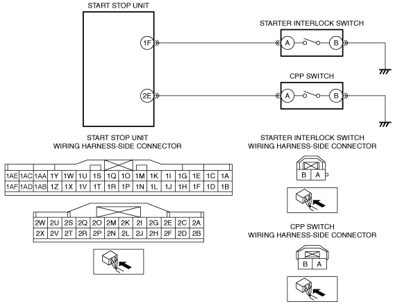
INSPECT FOR SHORT TO GROUND IN STARTER INTERLOCK SWITCH CIRCUIT
• Verify that the start stop unit and starter interlock switch connectors are disconnected.
• Inspect for continuity between starter interlock switch terminal A (wiring harness-side) and body ground.
• Is there continuity?
|
Yes
|
Refer to the wiring diagram and verify whether or not there is a common connector between start stop unit terminal 1F and starter interlock switch terminal A.
If there is a common connector:
• Determine the malfunctioning part by inspecting the common connector and the terminal for corrosion, damage, or pin disconnection, and the common wiring harness for a short to ground.
• Repair or replace the malfunctioning part.
If there is no common connector:
• Repair or replace the wiring harness which has a short to ground.
Go to Step 12.
|
|
No
|
Go to Step 12.
|
|
6
|
INSPECT CPP SWITCH CONNECTOR CONDITION
• Switch the ignition off.
• Disconnect the negative battery cable.
• Disconnect the CPP switch connector.
• Inspect the connector engagement and connection condition and inspect the terminals for damage, deformation, corrosion, or disconnection.
• Is the connector normal?
|
Yes
|
Go to the next step.
|
|
No
|
Repair or replace the connector, then go to Step 12.
|
|
7
|
INSPECT FOR OPEN CIRCUIT IN CPP SWITCH GROUND CIRCUIT
• Verify that the CPP switch connector is disconnected.
• Inspect for continuity between CPP switch terminal B (wiring harness-side) and body ground.
• Is there continuity?
|
Yes
|
Go to the next step.
|
|
No
|
Refer to the wiring diagram and verify whether or not there is a common connector between CPP switch terminal B and body ground.
If there is a common connector:
• Determine the malfunctioning part by inspecting the common connector and the terminal for corrosion, damage, or pin disconnection, and the common wiring harness for an open circuit.
• Repair or replace the malfunctioning part.
If there is no common connector:
• Repair or replace the wiring harness which has an open circuit.
Go to Step 12.
|
|
8
|
INSPECT CPP SWITCH
• Inspect the CPP switch.
• Is the CPP switch normal?
|
Yes
|
Go to the next step.
|
|
No
|
Replace the CPP switch, then go to the Step 12.
|
|
9
|
INSPECT START STOP UNIT CONNECTOR CONDITION
• Disconnect the start stop unit connector.
• Inspect the connector engagement and connection condition and inspect the terminals for damage, deformation, corrosion, or disconnection.
• Is the connector normal?
|
Yes
|
Go to the next step.
|
|
No
|
Repair or replace the connector, then go to Step 12.
|
|
10
|
INSPECT FOR OPEN CIRCUIT IN CPP SWITCH CIRCUIT
• Verify that the CPP switch and start stop unit connectors are disconnected.
• Inspect for continuity between start stop unit terminal 2E (wiring harness-side) and CPP switch terminal A (wiring harness-side).
• Is there continuity?
|
Yes
|
Go to Step 12.
|
|
No
|
Refer to the wiring diagram and verify whether or not there is a common connector between start stop unit terminal 2E and CPP switch terminal A.
If there is a common connector:
• Determine the malfunctioning part by inspecting the common connector and the terminal for corrosion, damage, or pin disconnection, and the common wiring harness for an open circuit.
• Repair or replace the malfunctioning part.
If there is no common connector:
• Repair or replace the wiring harness which has an open circuit.
Go to Step 12.
|
|
11
|
INSPECT START STOP UNIT CONNECTOR CONDITION
• Switch the ignition off.
• Disconnect the negative battery cable.
• Disconnect the start stop unit connector.
• Inspect the connector engagement and connection condition and inspect the terminals for damage, deformation, corrosion, or disconnection.
• Is the connector normal?
|
Yes
|
Go to the next step.
|
|
No
|
Repair or replace the connector, then go to the next step.
|
|
12
|
VERIFY THAT REPAIRS HAVE BEEN COMPLETED
• Always reconnect all disconnected connectors.
• Reconnect the negative battery cable.
• Clear the DTC for the start stop unit using the M-MDS.
• Switch the ignition ON (engine off or on).
• Perform the work of depressing and releasing the clutch pedal 3 times.
• Retrieve the start stop unit DTCs using the M-MDS.
• Is the same DTC displayed?
|
Yes
|
Repeat the inspection from Step 1.
• If the malfunction recurs, replace the start stop unit.
Go to the next step.
|
|
No
|
Go to the next step.
|
|
13
|
VERIFY IF OTHER DTCs DISPLAYED
• Are any other DTCs displayed?
|
Yes
|
Repair or replace the malfunctioning part according to the applicable DTC troubleshooting.
|
|
No
|
DTC troubleshooting completed.
|