 |
am6zzw00014444
DTC P0421:00 [SKYACTIV-D 2.2]
id0102s4704400
Details On DTCs
|
DESCRIPTION |
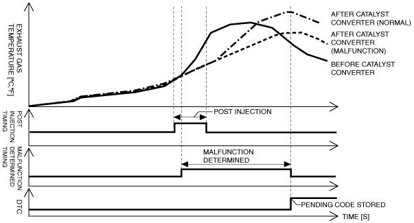
Catalyst efficiency below threshold |
|
|---|---|---|
|
DETECTION CONDITION
|
Determination conditions
|
• The difference between the exhaust gas temperature before and after passing the catalytic converter is specified value or less.
|
|
Preconditions
|
• Battery voltage: 8 V or more
• Engine speed: 1,200—2,000 rpm
• Fuel injection amount: 10—25 mm3/ stroke
• IAT (IAT sensor No.1): –10 °C {14 °F} or more
• Barometric pressure: 65 kPa {0.67 kgf/cm2, 9.5 psi} or more
• ECT: 60 °C {140 °F} or more
• Vehicle speed: 20—140 km/h {13.0—86.9 mph}
• Accumulated PM calculated from fuel injection amount: 0.8—4.0 g/l {0.05—0.25 lb/ft3}
• Amount of soot calculated based on difference in pressure between exhaust gas pressure before and after diesel particulate filter: 0.06—2.0 g/l {0.037—0.124 lb/ft3}
• Traveled distance after diesel particulate filter regeneration: 36—400 km {23—248 mile}
• Exhaust gas temperature before passing catalytic converter: 140—195 °C {284—383 °F} (MTX)
• Exhaust gas temperature before passing catalytic converter: 160—195 °C {320—383 °F} (ATX)
• Exhaust gas temperature after passing catalytic converter (at engine start): 0—200 °C {32—392 °F}
• Exhaust gas temperature after passing catalytic converter: 135—250 °C {275—482 °F}
|
|
|
Drive cycle
|
• 2
|
|
|
Self test type
|
• CMDTC self test
|
|
|
Sensor used
|
• Exhaust gas temperature sensor No.2
• Exhaust gas temperature sensor No.3
|
|
|
FAIL-SAFE FUNCTION
|
• Not applicable
|
|
|
VEHICLE STATUS WHEN DTCs ARE OUTPUT
|
• Check engine light is illuminated
|
|
|
POSSIBLE CAUSE
|
• Erratic signal to PCM
• Exhaust gas leakage from exhaust system
• Exhaust gas temperature sensor No.2 malfunction
• Exhaust gas temperature sensor No.3 malfunction
• Improper operation of fuel injector
• Catalytic converter or diesel particulate filter malfunction (deformation, damage)
• PCM malfunction
|
|
System Wiring Diagram
Function Explanation (DTC Detection Outline)
am6zzw00014444
|
Repeatability Verification Procedure
PID Item/Simulation Item Used In Diagnosis
PID/DATA monitor item table
|
Item |
Definition |
Unit |
Condition/Specification |
|---|---|---|---|
|
EXHTEMP2
|
Exhaust temperature sensor No.2
|
°C, °F
|
• Displays the exhaust gas temperature before passing catalytic converter
|
|
EXHTEMP3
|
Exhaust temperature sensor No.3
|
°C, °F
|
• Displays the exhaust gas temperature after passing catalytic converter
|
Function Inspection Using M-MDS
|
STEP |
INSPECTION |
ACTION |
|
|---|---|---|---|
|
1
|
PURPOSE: VERIFY RELATED SERVICE INFORMATION AVAILABILITY
• Verify related Service Information availability.
• Is any related Service Information available?
|
Yes
|
Perform repair or diagnosis according to the available Service Information.
• If the vehicle is not repaired, go to the next step.
|
|
No
|
Go to the next step.
|
||
|
2
|
PURPOSE: IDENTIFY TRIGGER DTC FOR FREEZE FRAME DATA
• Is the DTC P0421:00 on FREEZE FRAME DATA?
|
Yes
|
Go to the next step.
|
|
No
|
Go to the troubleshooting procedure for DTC on FREEZE FRAME DATA.
(See DTC TABLE [SKYACTIV-D 2.2].)
|
||
|
3
|
PURPOSE: RECORD VEHICLE STATUS AT TIME OF DTC DETECTION TO UTILIZE WITH REPEATABILITY VERIFICATION
• Record the FREEZE FRAME DATA/snapshot data on the repair order.
|
—
|
Go to the next step.
|
|
4
|
PURPOSE: VERIFY IF DIAGNOSTIC RESULT IS AFFECTED BY OTHER RELATED DTCs OCCURRING
• Switch the ignition off, then ON (engine off).
• Perform the Pending Trouble Code Access Procedure and DTC Reading Procedure.
• Is the other PENDING CODE/DTC also present?
|
Yes
|
Go to the applicable DTC inspection.
(See DTC TABLE [SKYACTIV-D 2.2].)
|
|
No
|
Go to the next step.
|
||
|
5
|
PURPOSE: VERIFY IF THERE IS PID ITEM CAUSING DRASTIC CHANGES OF ACCELERATION FLUCTUATION BY INPUT SIGNAL TO PCM AND DSC HU/CM
• Access the following PIDs using the M-MDS:
• Is there any signal that is far out of specification?
|
Yes
|
Go to the next step.
|
|
No
|
Go to the troubleshooting procedure to perform the procedure from Step 1.
|
||
|
6
|
PURPOSE: VERIFY CONNECTOR CONNECTIONS
• Access the following PIDs using the M-MDS:
• When the following parts are shaken, does the PID value include a PID item which has changed?
|
Yes
|
Inspect the related wiring harness and connector.
• Repair or replace the malfunctioning part.
Go to the troubleshooting procedure to perform the procedure from Step 5.
|
|
No
|
Go to the troubleshooting procedure to perform the procedure from Step 1.
|
||
Troubleshooting Diagnostic Procedure
Function Inspection Using M-MDS
|
STEP |
INSPECTION |
ACTION |
|
|---|---|---|---|
|
1
|
PURPOSE: INSPECT EXHAUST SYSTEM FOR LEAKAGE
• Visually inspect for exhaust gas leakage from the exhaust system.
• Is there any malfunction?
|
Yes
|
Repair or replace the malfunctioning part according to the inspection results, then go to Step 5.
|
|
No
|
Go to the next step.
|
||
|
2
|
PURPOSE: INSPECT EXHAUST GAS TEMPERATURE SENSOR NO.2
• Inspect the exhaust gas temperature sensor No.2.
• Is there any malfunction?
|
Yes
|
Replace the exhaust gas temperature sensor No.2, then go to Step 5.
|
|
No
|
Go to the next step.
|
||
|
3
|
PURPOSE: INSPECT EXHAUST GAS TEMPERATURE SENSOR NO.3
• Inspect the exhaust gas temperature sensor No.3.
• Is there any malfunction?
|
Yes
|
Replace the exhaust gas temperature sensor No.3, then go to Step 5.
|
|
No
|
Go to the next step.
|
||
|
4
|
PURPOSE: INSPECT FOR MALFUNCTION FUEL INJECTOR
• Inspect the fuel injector.
• Is there any malfunction?
|
Yes
|
Replace the suspect fuel injector, then go to the next step.
|
|
No
|
Catalytic converter or diesel particulate filter can be considered the cause.
• Replace the catalytic converter, then go to the next step.
|
||
|
5
|
PURPOSE: PERFORM DTC INSPECTION AND VERIFY IF MALFUNCTIONING PART IS PCM
• Always reconnect all disconnected connectors.
• Clear the DTC from the PCM memory using the M-MDS.
• Implement the repeatability verification procedure.
• Perform the Pending Trouble Code Access Procedure.
• Is the PENDING CODE for this DTC present?
|
Yes
|
Repeat the inspection from Step 1.
• If the malfunction recurs, replace the PCM.
Go to the next step.
|
|
No
|
Go to the next step.
|
||
|
6
|
PURPOSE: VERIFY AFTER REPAIR PROCEDURE
• Perform the “AFTER REPAIR PROCEDURE”.
• Are any DTCs present?
|
Yes
|
Go to the applicable DTC inspection.
(See DTC TABLE [SKYACTIV-D 2.2].)
|
|
No
|
DTC troubleshooting completed.
|
||