|
1
|
VERIFY IF MALFUNCTION CAUSED BY ENGINE MALFUNCTION
• Verify the vehicle engine condition.
• Can malfunction symptoms other than “NO.14 POOR FUEL ECONOMY” be verified?
|
Yes
|
Go to the applicable symptom troubleshooting.
|
|
No
|
Go to the next step.
|
|
2
|
INSPECT COOLING SYSTEM FOR MALFUNCTION
• Is any cooling system concern (overheating, runs cold) present?
|
Yes
|
Perform the applicable symptom troubleshooting.
|
|
No
|
Go to the next step.
|
|
3
|
VERIFY PCM DTC
• Retrieve any DTCs using the M-MDS.
• Are any DTCs present?
|
Yes
|
Go to the applicable DTC inspection.
|
|
No
|
Go to the next step.
|
|
4
|
VERIFY CURRENT INPUT SIGNAL STATUS
-
Caution
-
• While performing this step, always operate the vehicle in a safe and lawful manner.
• When the M-MDS is used to observe monitor system status while driving, be sure to have another technician with you, or record the data in the M-MDS using the PID/DATA MONITOR AND RECORD capturing function and inspect later.
• Access the following PIDs using the M-MDS:
-
― APP1
― APP2
― ECT
― IAT
― MAF
― MAP
― TP_REL
• Do the PIDs indicate the correct values under the trouble condition?
|
Yes
|
Go to the next step.
|
|
No
|
APP1, APP2 PIDs are not as specified:
• Inspect the APP sensor.
ECT PID is not as specified:
• Inspect the ECT sensor.
IAT PID is not as specified:
• Inspect the IAT sensor No.1.
MAF PID is not as specified:
• Inspect the MAF sensor.
MAP PID is not as specified:
• Inspect the MAP sensor.
TP_REL PID is not as specified:
Repair or replace the malfunctioning part according to the inspection results.
• If the malfunction remains:
-
― Perform the “INTERMITTENT CONCERN TROUBLESHOOTING” procedure.
|
|
5
|
DETERMINE IF MALFUNCTION CAUSE IS A/C REQUEST SIGNAL OR OTHER
• Access the AC_REQ PID using the M-MDS.
• Monitor the AC_REQ PID while turning on and off the air conditioner with switch on the control panel.
• Does the AC_REQ PID value change from on to off according to switch control panel?
|
Yes
|
Go to the next step.
|
|
No
|
If the AC_REQ PID is always ON:
• Perform the symptom troubleshooting “NO.24 A/C IS ALWAYS ON OR A/C COMPRESSOR RUNS CONTINUOUSLY”.
If the AC_REQ PID is always OFF:
• Perform the symptom troubleshooting “NO.23 A/C DOES NOT WORK SUFFICIENTLY”.
|
|
6
|
INSPECT FUEL INJECTOR OPERATION
• Perform the Fuel Injector Operation Inspection.
• Do the fuel injectors operate properly?
|
Yes
|
Go to the next step.
|
|
No
|
Repair or replace the malfunctioning part according to the inspection results.
|
|
7
|
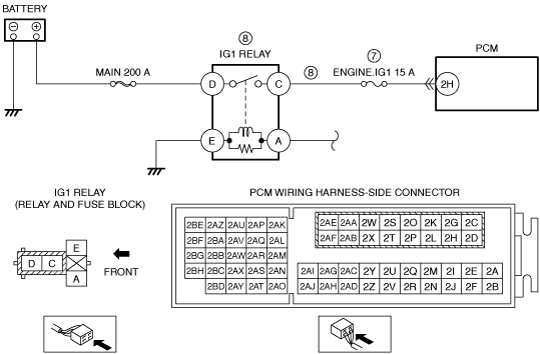
INSPECT ENGINE.IG1 15 A FUSE
• Switch the ignition off.
• Remove the ENGINE.IG1 15 A fuse.
• Inspect the ENGINE.IG1 15 A fuse.
• Is there any malfunction?
|
Yes
|
If the fuse is blown:
• Refer to the wiring diagram and verify whether or not there is a common connector between ENGINE.IG1 15 A fuse and PCM terminal 2H.
If there is a common connector:
-
― Determine the malfunctioning part by inspecting the common connector and the terminal for corrosion, damage, or pin disconnection, and the common wiring harness for a short to ground.
― Repair or replace the malfunctioning part.
If there is no common connector:
-
― Repair or replace the wiring harness which has a short to ground.
― Replace the fuse.
If the fuse is damaged:
• Replace the fuse.
Go to the next step.
|
|
No
|
Reinstall the ENGINE.IG1 15 A fuse, then go to the next step.
|
|
8
|
INSPECT IG1 RELAY CIRCUIT FOR SHORT TO POWER SUPPLY
• Remove the IG1 relay.
• Disconnect the PCM connector.
• Measure the voltage at the IG1 relay terminal C (wiring harness-side).
• Is the voltage 0 V?
|
Yes
|
Inspect the IG1 relay.
• If there is any malfunction:
-
― Replace the IG1 relay.
• If there is no malfunction:
-
― Reconnect all disconnected connectors.
― Go to the next step.
|
|
No
|
Refer to the wiring diagram and verify whether or not there is a common connector between IG1 relay terminal C and PCM terminal 2H.
If there is a common connector:
• Determine the malfunctioning part by inspecting the common connector and the terminal for corrosion, damage, or pin disconnection, and the common wiring harness for a short to power supply.
• Repair or replace the malfunctioning part.
If there is no common connector:
• Repair or replace the wiring harness which has a short to power supply.
|
|
9
|
INSPECT RELATED PART CONDITION
• Inspect the following:
-
― Air cleaner element for contamination
― Intake-air system restriction
― Fuel quality (proper octane, contamination, winter/summer blend)
― Coolant level
― Clutch slippage (MTX)
― ATF level (ATX)
― Brake dragging
― Tire air pressure
― Vacuum leakage
― Fuel leakage
― MAF sensor contaminated
― Tires, wheels (large size)
― Change of intake air system components and exhaust system components
― Engine operation time is longer than traveled distance
-
• Vehicle is driven in congested traffic frequently
• Left idling for long periods
― Amount of fuel injection increases
-
• Overloaded
• Frequent acceleration/deceleration
• Frequently driving on ascending roads
• Travel distance per one drive is short (amount of time for warm-up is long during engine operation)
• Improper load signal input
― Discharge is high when the vehicle is not used
-
• Driver forgets to switch electronic device off
• Electronic device is frequently used with engine stopped (no power generation)
• Remote transmitter is left in vehicle with engine stopped (no power generation) (with advanced keyless entry system)
• Vehicle left undriven for long periods
• Large amount of parasitic draw (especially after-market electronic devices)
― CKP sensor, intake CMP sensor and exhaust CMP sensor
-
• Damaged trigger wheel, intake camshaft and exhaust camshaft
• Is there any malfunction?
|
Yes
|
Service if necessary.
• Repeat this step.
|
|
No
|
Go to the next step.
|
|
10
|
INSPECT FUEL PRESSURE (HIGH-SIDE)
• Start the engine and warm it up completely.
• Access the FUEL_PRES PID using the M-MDS at idle.
• Is the FUEL_PRES PID value approx. 3 MPa {31 kgf/cm2, 435 psi}?
|
Yes
|
Go to Step 14.
|
|
No
|
Lower than 3 MPa {31 kgf/cm2, 435 psi}:
• Inspect the following:
-
― Fuel leakage at the fuel line and fuel injector
― Fuel pump
-
• Perform the Fuel Pump (Low-pressure Side) Operation Inspection.
― High pressure fuel pump
• If there is any malfunction:
-
― Repair or replace the malfunctioning part according to the inspection results.
• If there is no malfunction:
-
― Go to Step 13.
Higher than 3 MPa {31 kgf/cm2, 435 psi}:
• Go to the next step.
|
|
11
|
DETERMINE IF MALFUNCTION CAUSE IS FUEL PRESSURE SENSOR OR HIGH PRESSURE FUEL PUMP
• Is the vehicle acceleration performance normal?
|
Yes
|
Go to the next step.
|
|
No
|
Go to Step 13.
|
|
12
|
INSPECT FUEL PRESSURE SENSOR
• Inspect the fuel pressure sensor.
• Is there any malfunction?
|
Yes
|
Replace the fuel distributor.
|
|
No
|
Go to Step 14.
|
|
13
|
INSPECT SPILL VALVE CONTROL SOLENOID VALVE CONTROL CIRCUIT FOR SHORT TO GROUND
• Switch the ignition off.
• Disconnect the high pressure fuel pump and PCM connectors.
• Inspect for continuity between high pressure fuel pump terminal A (wiring harness-side) and body ground.
• Is there continuity?
|
Yes
|
Refer to the wiring diagram and verify whether or not there is a common connector between high pressure fuel pump terminal A and PCM terminal 1EE.
If there is a common connector:
• Determine the malfunctioning part by inspecting the common connector and the terminal for corrosion, damage, or pin disconnection, and the common wiring harness for a short to ground.
• Repair or replace the malfunctioning part.
If there is no common connector:
• Repair or replace the wiring harness which has a short to ground.
If the malfunction remains:
• Replace the PCM. (damage to driver in PCM)
|
|
No
|
Replace the high pressure fuel pump.
|
|
14
|
INSPECT FUEL PRESSURE (LOW-SIDE)
• Connect the fuel pressure gauge between fuel pump and high pressure fuel pump.
• Measure the low side fuel pressure.
• Is the low side fuel pressure within specification?
Specification:
• 405—485 kPa {4.13—4.94 kgf/cm2, 58.8—70.3 psi}
|
Yes
|
Go to the next step.
|
|
No
|
Inspect the following:
• Fuel line restriction
• Fuel filter clogged
-
― If there is any malfunction:
-
• Repair or replace the malfunctioning part according to the inspection results.
― If there is no malfunction:
-
• Replace the fuel pump unit.
|
|
15
|
INSPECT ENGINE COMPRESSION
• Measure the compression pressure for each cylinder.
• Are compression pressures within specification?
Specification:
• Compression [SKYACTIV-G 1.5]
-
― Standard: 888 kPa {9.05 kgf/cm2, 129 psi} (300 rpm)
― Minimum: 710 kPa {7.24 kgf/cm2, 103 psi} (300 rpm)
― Maximum difference between cylinders: 151 kPa {1.54 kgf/cm2, 21.9 psi} (300 rpm)
• Compression [SKYACTIV-G 2.0, European (L.H.D. U.K.) specs.]
-
― Standard: 978 kPa {9.97 kgf/cm2, 142 psi} (300 rpm)
― Minimum: 783 kPa {7.98 kgf/cm2, 114 psi} (300 rpm)
― Maximum difference between cylinders: 166 kPa {1.69 kgf/cm2, 24.1 psi} (300 rpm)
• Compression [SKYACTIV-G 2.0, Except European (L.H.D. U.K.) specs.]
-
― Standard: 885 kPa {9.02 kgf/cm2, 128 psi} (300 rpm)
― Minimum: 708 kPa {7.22 kgf/cm2, 103 psi} (300 rpm)
― Maximum difference between cylinders: 150 kPa {1.53 kgf/cm2, 21.8 psi} (300 rpm)
• Compression [SKYACTIV-G 2.5]
-
― Standard: 954 kPa {9.73 kgf/cm2, 138 psi} (300 rpm)
― Minimum: 763 kPa {7.78 kgf/cm2, 111 psi} (300 rpm)
― Maximum difference between cylinders: 161 kPa {1.64 kgf/cm2, 23.4 psi} (300 rpm)
-
Note
-
• Because the SKYACTIV-G retards the intake valve closing timing, compression pressure is low.
|
Yes
|
Go to Step 21.
|
|
No
|
Go to the next step.
|
|
16
|
INSPECT ELECTRIC VARIABLE VALVE TIMING DRIVER
• Inspect the electric variable valve timing driver.
• Is there any malfunction?
|
Yes
|
Replace the electric variable valve timing motor/driver.
|
|
No
|
Go to the next step.
|
|
17
|
INSPECT ELECTRIC VARIABLE VALVE TIMING MOTOR
• Inspect the electric variable valve timing motor.
• Is there any malfunction?
|
Yes
|
Replace the electric variable valve timing motor/driver.
|
|
No
|
Go to the next step.
|
|
18
|
INSPECT ELECTRIC VARIABLE VALVE TIMING ACTUATOR
• Inspect the electric variable valve timing actuator.
• Is there any malfunction?
|
Yes
|
Replace the electric variable valve timing actuator.
|
|
No
|
Go to the next step.
|
|
19
|
INSPECT HYDRAULIC VARIABLE VALVE TIMING CONTROL SYSTEM OPERATION
• Perform the Hydraulic Variable Valve Timing Control System Operation Inspection.
• Is there any malfunction?
|
Yes
|
Repair or replace the malfunctioning part according to the inspection results.
|
|
No
|
Go to the next step.
|
|
20
|
INSPECT FOR MALFUNCTION DUE TO DEVIATED VALVE TIMING
• Inspect the valve timing (timing chain installation condition).
• Is the valve timing normal?
|
Yes
|
Inspect for the following engine internal parts:
• Cylinder
• Piston ring
• Intake valve
• Exhaust valve
• Such as cylinder head gasket
-
― If there is any malfunction:
-
• Repair or replace the malfunctioning part according to the inspection results.
|
|
No
|
Adjust the valve timing to the correct timing.
|
|
21
|
INSPECT IGNITION SYSTEM OPERATION
• Perform the Spark Test.
• Is the strong blue spark visible at each cylinder?
|
Yes
|
Go to the next step.
|
|
No
|
Repair or replace the malfunctioning part according to the inspection results.
|
|
22
|
INSPECT EXHAUST SYSTEM FOR RESTRICTION
• Inspect for restriction in the exhaust system and the TWC.
• Is there any restriction?
|
Yes
|
Repair or replace the malfunctioning part according to the inspection results.
|
|
No
|
Go to the next step.
|
|
23
|
INSPECT IF MALFUNCTION CAUSE IS PCV VALVE OR INJECTOR DRIVER (PCM INTEGRATED)
• Is there any malfunction?
|
Yes
|
Replace the PCV valve.
|
|
No
|
Injector driver malfunction.
If the problem remains, overhaul the engine.
|
|
24
|
Verify the test results.
• If normal, return to the diagnostic index to service any additional symptoms.
• If a malfunction remains, inspect the related Service Information and perform the repair or diagnosis.
-
― If the vehicle is repaired, troubleshooting is completed.
― If the vehicle is not repaired or additional diagnostic information is not available, replace the PCM.
|