 |
am3zzw00017446
SUPPLY PUMP REMOVAL/INSTALLATION [SKYACTIV-D 1.5]
id0114q2805700
Operation After Replacing Supply Pump
1. If the supply pump is replaced, perform the following procedure.
|
STEP |
ACTION |
PAGE/CONDITION |
|---|---|---|
|
1
|
Perform supply pump data reset procedure.
|
|
|
2
|
Switch the ignition off.
|
—
|
|
3
|
Wait for 20 s or more.
|
—
|
|
4
|
Perform KOEO self-test procedure.
|
|
|
5
|
Maintain the idle status for 30 s with the following condition met.
• ECT: 60—100 °C {140—212 °F}
|
—
|
|
6
|
Perform KOER self-test procedure.
|
Supply Pump Removal/Installation
1. Disconnect the negative battery cable. (See NEGATIVE BATTERY CABLE DISCONNECTION/CONNECTION [SKYACTIV-D 1.5].)
2. Remove the engine cover. (See ENGINE COVER REMOVAL/INSTALLATION [SKYACTIV-D 1.5].)
3. Complete the “BEFORE SERVICE PRECAUTION”. (See BEFORE SERVICE PRECAUTION [SKYACTIV-D 1.5].)
4. Remove the following parts as a single unit: (See INTAKE-AIR SYSTEM REMOVAL/INSTALLATION [SKYACTIV-D 1.5].)
5. Remove the battery and the battery tray. (See BATTERY REMOVAL/INSTALLATION [SKYACTIV-D 1.5].)
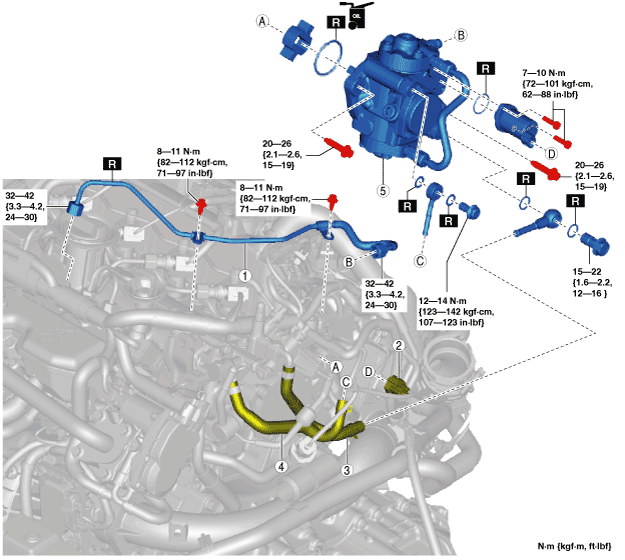
6. Remove in the order shown in the figure.
7. Install in the reverse order of removal.
8. Complete the “AFTER SERVICE PRECAUTION”. (See AFTER SERVICE PRECAUTION [SKYACTIV-D 1.5].)
am3zzw00017446
|
|
1
|
Injection pipe (supply pump side)
|
|
2
|
Suction control valve connector
|
|
3
|
Fuel main hose
|
|
4
|
Fuel return hose
|
|
5
|
Supply pump
(See Supply pump removal note.)
|
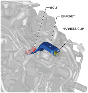
Supply pump removal note
1. Remove the wiring harness clip and bolt shown in the figure and set the bracket aside to a location which does not interfere with the servicing.
am2zzw00012130
|
2. Disconnect the ECT sensor connector. (See ENGINE COOLANT TEMPERATURE (ECT) SENSOR REMOVAL/INSTALLATION [SKYACTIV-D 1.5].)
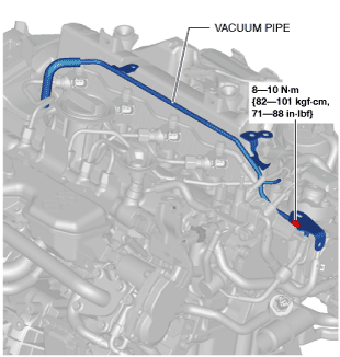
3. Remove the vacuum pipe.
am3zzw00017447
|
4. Remove the supply pump.
Supply pump installation note
1. Install the supply pump.
2. Install the vacuum pipe.
am3zzw00017448
|
3. Connect the ECT sensor connector. (See ENGINE COOLANT TEMPERATURE (ECT) SENSOR REMOVAL/INSTALLATION [SKYACTIV-D 1.5].)
4. Install the bracket as shown in the figure.
ac3wzw00001431
|
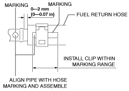
Fuel return hose installation note
1. Install fuel return hose as shown in the figure.
ac3wzw00001432
|
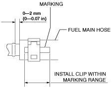
Fuel main hose installation note
1. Install fuel main hose as shown in the figure.
ac3wzw00001433
|
Injection pipe (supply pump side) installation note
1. Temporarily tighten the injection pipe (supply pump side).
2. Temporarily tighten the injection pipe (supply pump side) bracket.
3. Tighten the injection pipe (supply pump side).
4. Tighten the injection pipe (supply pump side) bracket.