DTC U0301:09/U0401:00 [DYNAMIC STABILITY CONTROL (DSC)]


id0402b2893900

DTC
U0301:09, U0401:00
Abnormal message from PCM
DETECTION CONDITION
•  Correct data cannot be received from PCM
FAIL-SAFE FUNCTION
•  U0301:09
―  Illuminates the Mazda Radar Cruise Control (MRCC) warning light.
―  Inhibits the Mazda Radar Cruise Control (MRCC) control.
•  U0401:00
―  Illuminates the TCS/DSC indicator light*1, Mazda Radar Cruise Control (MRCC) warning light*1*2, and Smart Brake Support/Smart City Brake Support (SBS/SCBS) indicator light (amber)*1*2.
―  Tire pressure monitoring system warning light*2 illuminates after flashes. (Not illuminated/flashed depending on malfunction content.)
―  Inhibits the TCS*3, DSC*3, vehicle roll prevention function*2*3, Hill Launch Assist (HLA)*3, TPMS*2*3, Secondary Collision Reduction (SCR)*2*3, Mazda Radar Cruise Control (MRCC)*2*3, Smart Brake Support (SBS)*2*3, and Smart City Brake Support (SCBS)*2*3 controls.
*1: Not illuminated depending on malfunction content.
*2: If equipped.
*3: Control enabled depending on malfunction content.
POSSIBLE CAUSE
•  DTCs are stored in the PCM
•  DTCs are stored in the TCM
•  Short to ground or open circuit in backup voltage circuit
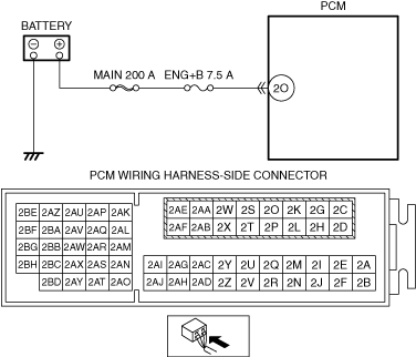
―  Short to ground in wiring harness between MAIN 200 A fuse and PCM terminal 2O
―  MAIN 200 A fuse and/or ENG+B 7.5 A fuse malfunction
―  Open circuit in wiring harness between battery positive terminal and PCM terminal 2O
•  PCM malfunction
•  TCM malfunction

Diagnostic procedure

STEP

INSPECTION

ACTION

1
PERFORM PCM DTC INSPECTION
•  Switch the ignition off.
•  Are any DTCs detected?
Yes
Go to applicable DTC inspection.
No
Go to the next step.
2
INSPECT BACKUP VOLTAGE CIRCUIT FOR SHORT TO GROUND OR OPEN CIRCUIT
•  Reconnect all disconnected connectors.
•  Verify the VPWR PID value.
•  Is the VPWR PID value B+?
Yes
Go to the next step.
No
Inspect the MAIN 200 A fuse and ENG+B 7.5 A fuse.
•  If the fuse is blown:
―  Refer to the wiring diagram and verify whether or not there is a common connector between MAIN 200 A fuse and PCM terminal 2O.
If there is a common connector:
•  Determine the malfunctioning part by inspecting the common connector and the terminal for corrosion, damage, or pin disconnection, and the common wiring harness for a short to ground.
•  Repair or replace the malfunctioning part.
If there is no common connector:
•  Repair or replace the wiring harness which has a short to ground.
•  Replace the fuse.
•  If the fuse is damaged:
―  Replace the fuse.
•  If all fuses are normal:
―  Refer to the wiring diagram and verify whether or not there is a common connector between battery positive terminal and PCM terminal 2O.
If there is a common connector:
•  Determine the malfunctioning part by inspecting the common connector and the terminal for corrosion, damage, or pin disconnection, and the common wiring harness for an open circuit.
•  Repair or replace the malfunctioning part.
If there is no common connector:
•  Repair or replace the wiring harness which has an open circuit.
Go to the next step.
3
DETERMINE IF MALFUNCTION IS PCM, TCM
•  Is the PCM normal?
Yes
Go to the next step.
No
Replace the PCM, then go to the next step.
4
VERIFY THAT THE SAME DTC IS NOT PRESENT
•  Clear the DTCs from the memory.
•  Are the same DTCs present?
Yes
Repeat the inspection from Step 1.
Go to the next step.
No
Go to the next step.
5
VERIFY IF OTHER DTCs DISPLAYED
•  Are any other DTCs displayed?
Yes
Go to the applicable DTC inspection.
No
DTC troubleshooting completed.