 |
am3zzw00017317
CLUTCH PIPE AND HOSE REMOVAL/INSTALLATION [C66M-R]
id0510ma157000
SKYACTIV-G 1.5, SKYACTIV-G 2.0, SKYACTIV-G 2.5
1. Disconnect the negative battery cable. (See NEGATIVE BATTERY CABLE DISCONNECTION/CONNECTION [SKYACTIV-G 1.5, SKYACTIV-G 2.0, SKYACTIV-G 2.5].)
2. Remove the air cleaner and air hose as a single unit. (See INTAKE-AIR SYSTEM REMOVAL/INSTALLATION [SKYACTIV-G 1.5, SKYACTIV-G 2.0, SKYACTIV-G 2.5].)
3. Remove the battery tray and PCM component. (See BATTERY REMOVAL/INSTALLATION [SKYACTIV-G 1.5, SKYACTIV-G 2.0, SKYACTIV-G 2.5].)
4. Remove the cowl panel. (R.H.D.) (See COWL PANEL REMOVAL/INSTALLATION.)
5. Remove the insulator. (R.H.D.) (See EXHAUST SYSTEM REMOVAL/INSTALLATION [SKYACTIV-G 1.5, SKYACTIV-G 2.0, SKYACTIV-G 2.5].)
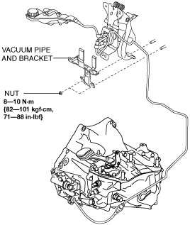
6. Disconnect the vacuum pipe and bracket. (R.H.D.)
am3zzw00017317
|
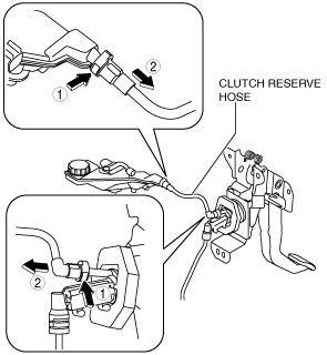
7. Remove the clutch reserve hose while pressing the point indicated by the arrow in the figure.
am6zzw00013175
|
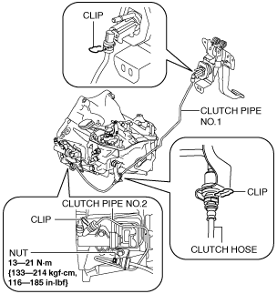
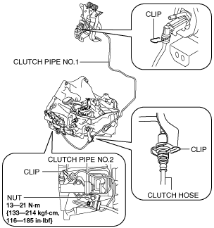
8. Remove the clutch pipe and hose using the following procedure:
L.H.D.
am6zzw00013176
|
R.H.D.
am6zzw00013177
|
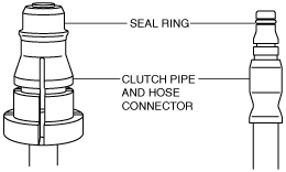
9. Verify that the seal ring is installed to the clutch pipe and hose connector.
am5ezw00005449
|
10. Install the clutch pipe and hose.
11. Insert the clutch reserve hose connector straight.
12. Pull each engagement of the clutch reserve hose and clutch pipe and hose, verify that they are engaged, and then press all of them again.
13. Install in the reverse order of removal.
14. Bleed the air from the clutch system. (See CLUTCH FLUID REPLACEMENT/AIR BLEEDING [C66M-R].)
SKYACTIV-D 1.5
1. Disconnect the negative battery cable. (See NEGATIVE BATTERY CABLE DISCONNECTION/CONNECTION [SKYACTIV-D 1.5].)
2. Remove the air cleaner, air hose and fresh air duct as a single unit. (See INTAKE-AIR SYSTEM REMOVAL/INSTALLATION [SKYACTIV-D 1.5].)
3. Remove the battery and battery tray. (See BATTERY REMOVAL/INSTALLATION [SKYACTIV-D 1.5].)
4. Remove the cowl panel. (R.H.D.) (See COWL PANEL REMOVAL/INSTALLATION.)
5. Remove the insulator. (R.H.D.) (See EXHAUST SYSTEM REMOVAL/INSTALLATION [SKYACTIV-D 1.5].)
6. Disconnect the vacuum pipe and bracket. (R.H.D.)
am3zzw00017317
|
7. Remove the clutch reserve hose while pressing the point indicated by the arrow in the figure.
am6zzw00013175
|
8. Remove the clutch pipe and hose using the following procedure:
L.H.D.
am6zzw00013176
|
R.H.D.
am6zzw00013177
|
9. Verify that the seal ring is installed to the clutch pipe and hose connector.
am5ezw00005449
|
10. Install the clutch pipe and hose.
11. Insert the clutch reserve hose connector straight.
12. Pull each engagement of the clutch reserve hose and clutch pipe and hose, verify that they are engaged, and then press all of them again.
13. Install in the reverse order of removal.
14. Bleed the air from the clutch system. (See CLUTCH FLUID REPLACEMENT/AIR BLEEDING [C66M-R].)