 |
am3zzw00017918
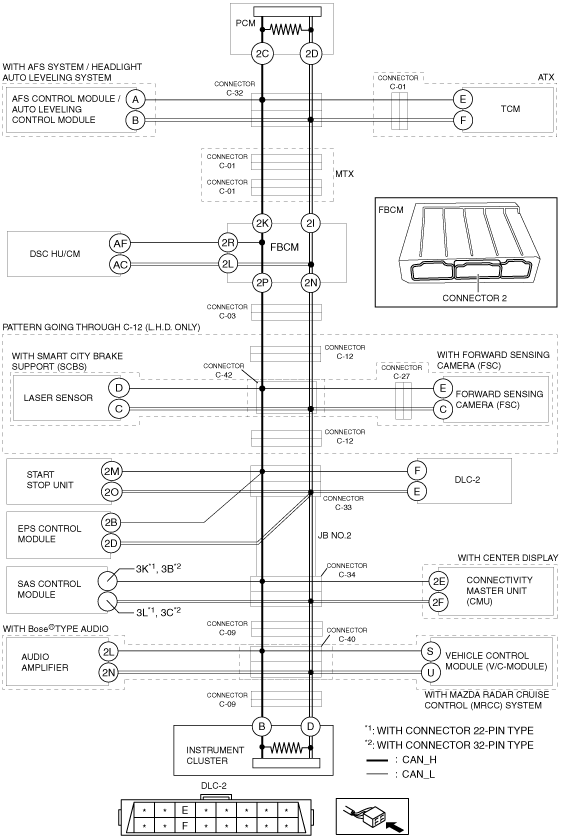
DETERMINING SHORT BETWEEN CIRCUITS LOCATION (HS-CAN) [SKYACTIV-D 1.5]
id100218000800
System Wiring Diagram
am3zzw00017918
|
Determination Procedure
|
Step |
Inspection |
Action |
|
|---|---|---|---|
|
1
|
INSPECT BETWEEN FRONT BODY CONTROL MODULE (FBCM) AND INSTRUMENT CLUSTER FOR SHORT BETWEEN CIRCUITS
• Disconnect the negative battery cable.
• Disconnect connector 2 which has front body control module (FBCM) terminals 2P and 2N.
• Connect the negative battery cable.
• Switch the ignition ON (engine off).
• Measure the voltage at DLC-2 terminals F and E.
• Is the voltage at DLC-2 terminals F and E the same?
|
Yes
|
Go to Step 13.
|
|
No
|
Go to the next step.
|
||
|
2
|
INSPECT FRONT BODY CONTROL MODULE (FBCM) FOR SHORT BETWEEN CIRCUITS
• Switch the ignition off.
• Disconnect the negative battery cable.
• Inspect for continuity between front body control module (FBCM) terminals 2P and 2N.
• Is there continuity?
|
Yes
|
Replace the front body control module (FBCM) because there is a short between circuits in the front body control module (FBCM).
|
|
No
|
Go to the next step.
|
||
|
3
|
INSPECT BETWEEN DSC HU/CM AND FRONT BODY CONTROL MODULE (FBCM) FOR SHORT BETWEEN CIRCUITS
• Inspect for continuity between DSC HU/CM terminals AF and AC.
• Is there continuity?
|
Yes
|
Go to the next step.
|
|
No
|
• Go to Step 5.(ATX)
• Go to Step 6.(MTX)
|
||
|
4
|
INSPECT OR DSC HU/CM FOR SHORT BETWEEN CIRCUITS
• Disconnect the DSC HU/CM connector.
• Inspect for continuity between DSC HU/CM terminals AF and AC (wiring harness side).
• Is there continuity?
|
Yes
|
Repair or replace the wiring harness between the DSC HU/CM and front body control module (FBCM) because the wiring harness is shorted between circuits.
|
|
No
|
Replace the DSC HU/CM because there is a short between circuits in the DSC HU/CM.
|
||
|
5
|
INSPECT BETWEEN CONNECTOR C-32 AND FRONT BODY CONTROL MODULE (FBCM) FOR SHORT BETWEEN CIRCUITS
• Switch the ignition off.
• Disconnect the negative battery cable.
• Disconnect connector C-32.
• Connect connector 2 which has front body control module (FBCM) terminals 2P and 2N.
• Connect the negative battery cable.
• Switch the ignition ON (engine off).
• Measure the voltage at DLC-2 terminals F and E.
• Is the voltage at DLC-2 terminals F and E the same?
|
Yes
|
Repair or replace the wiring harness between connector C-32 and front body control module (FBCM) because the wiring harness is shorted between circuits.
|
|
No
|
Go to Step 8.
|
||
|
6
|
INSPECT BETWEEN CONNECTOR C-01 AND FRONT BODY CONTROL MODULE (FBCM) FOR SHORT BETWEEN CIRCUITS
• Switch the ignition off.
• Disconnect the negative battery cable.
• Disconnect connector C-01.
• Connect connector 2 which has front body control module (FBCM) terminals 2P and 2N.
• Connect the negative battery cable.
• Switch the ignition ON (engine off).
• Measure the voltage at DLC-2 terminals F and E.
• Is the voltage at DLC-2 terminals F and E the same?
|
Yes
|
Repair or replace the wiring harness between connector C-01 and front body control module (FBCM) because the wiring harness is shorted between circuits.
|
|
No
|
Go to the next step.
|
||
|
7
|
INSPECT BETWEEN CONNECTOR C-32 AND CONNECTOR C-01 FOR SHORT BETWEEN CIRCUITS
• Switch the ignition off.
• Disconnect the negative battery cable.
• Disconnect connector C-32.
• Connect connector C-01.
• Connect the negative battery cable.
• Switch the ignition ON (engine off).
• Measure the voltage at DLC-2 terminals F and E.
• Is the voltage at DLC-2 terminals F and E the same?
|
Yes
|
Repair or replace the wiring harness between connector C-32 and connector C-01 because the wiring harness is shorted between circuits.
|
|
No
|
Go to the next step.
|
||
|
8
|
INSPECT BETWEEN AFS CONTROL MODULE / AUTO LEVELING CONTROL MODULE AND CONNECTOR C-32 FOR SHORT BETWEEN CIRCUITS
• Inspect for continuity between AFS control module / auto leveling control module terminals A and B.
• Is there continuity?
|
Yes
|
Go to the next step.
|
|
No
|
Go to Step 10.
|
||
|
9
|
INSPECT AFS CONTROL MODULE / AUTO LEVELING CONTROL MODULE FOR SHORT BETWEEN CIRCUITS
• Disconnect the AFS control module / auto leveling control module connector.
• Inspect for continuity between AFS control module / auto leveling control module terminals A and B (wiring harness side).
• Is there continuity?
|
Yes
|
Repair or replace the wiring harness between the AFS control module / auto leveling control module and connector C-32 because the wiring harness is shorted between circuits.
|
|
No
|
Replace the AFS control module / auto leveling control module because there is a short between circuits in the AFS control module / auto leveling control module.
|
||
|
10
|
INSPECT BETWEEN TCM AND CONNECTOR C-32 FOR SHORT BETWEEN CIRCUITS
• Inspect for continuity between TCM terminals E and F.
• Is there continuity?
|
Yes
|
Go to the next step.
|
|
No
|
Repair or replace the wiring harness between the front body control module (FBCM) and connector C-32 because the wiring harness is shorted between circuits.
|
||
|
11
|
INSPECT BETWEEN TCM AND CONNECTOR C-01 FOR SHORT BETWEEN CIRCUITS
• Disconnect connector C-01.
• Inspect for continuity between TCM terminals E and F.
• Is there continuity?
|
Yes
|
Go to the next step.
|
|
No
|
Repair or replace the wiring harness between connector C-01 and connector C-32 because the wiring harness is shorted between circuits.
|
||
|
12
|
INSPECT TCM FOR SHORT BETWEEN CIRCUITS
• Disconnect the TCM connector.
• Inspect for continuity between TCM terminals E and F (wiring harness side).
• Is there continuity?
|
Yes
|
Repair or replace the wiring harness between the TCM and connector C-01 because the wiring harness is shorted between circuits.
|
|
No
|
Replace the TCM because there is a short between circuits in the TCM.
|
||
|
13
|
INSPECT BETWEEN CONNECTOR C-03 AND INSTRUMENT CLUSTER FOR SHORT BETWEEN CIRCUITS
• Switch the ignition off.
• Disconnect the negative battery cable.
• Disconnect connector C-03.
• Connect the negative battery cable.
• Switch the ignition ON (engine off).
• Measure the voltage at DLC-2 terminals F and E.
• Is the voltage at DLC-2 terminals F and E the same?
|
Yes
|
Go to the next step.
|
|
No
|
Repair or replace the wiring harness between front body control module (FBCM) and connector C-03 because the wiring harness is shorted between circuits.
|
||
|
14
|
INSPECT BETWEEN CONNECTOR C-12 AND INSTRUMENT CLUSTER FOR SHORT BETWEEN CIRCUITS
• Switch the ignition off.
• Disconnect the negative battery cable.
• Disconnect connector C-12.
• Connect the negative battery cable.
• Switch the ignition ON (engine off).
• Measure the voltage at DLC-2 terminals F and E.
• Is the voltage at DLC-2 terminals F and E the same?
|
Yes
|
Go to Step 21.
|
|
No
|
Go to the next step.
|
||
|
15
|
INSPECT BETWEEN LASER SENSOR / FORWARD SENSING CAMERA (FSC) AND CONNECTORS C-12 FOR SHORT BETWEEN CIRCUITS
• Switch the ignition off.
• Disconnect the negative battery cable.
• Inspect for continuity between laser sensor terminals D and C (with smart city brake support (SCBS)).
• Inspect for continuity between forward sensing camera (FSC) terminals E and C (with forward sensing camera (FSC)).
• Is there continuity?
|
Yes
|
Go to the next step.
|
|
No
|
Repair or replace the wiring harness between connector C-03 and connector C-12 because the wiring harness is shorted between circuits.
|
||
|
16
|
INSPECT BETWEEN CONNECTOR C-42 AND LASER SENSOR FOR SHORT BETWEEN CIRCUITS
• Disconnect connector C-42.
• Inspect for continuity between laser sensor terminals D and C.
• Is there continuity?
|
Yes
|
Go to the next step.
|
|
No
|
Go to Step 18.
|
||
|
17
|
INSPECT LASER SENSOR FOR SHORT BETWEEN CIRCUITS
• Disconnect the laser sensor connector.
• Inspect for continuity between laser sensor terminals D and C (wiring harness side).
• Is there continuity?
|
Yes
|
Repair or replace the wiring harness between the laser sensor and connector C-42 because the wiring harness is shorted between circuits.
|
|
No
|
Replace the laser sensor because there is a short between circuits in the laser sensor.
|
||
|
18
|
INSPECT BETWEEN FORWARD SENSING CAMERA (FSC) AND CONNECTOR C-42 FOR SHORT BETWEEN CIRCUITS
• Inspect for continuity between forward sensing camera (FSC) terminals E and C.
• Is there continuity?
|
Yes
|
Go to the next step.
|
|
No
|
Repair or replace the wiring harness between connector C-12 and connector C-42 because the wiring harness is shorted between circuits.
|
||
|
19
|
INSPECT BETWEEN FORWARD SENSING CAMERA (FSC) AND CONNECTOR C-27 FOR SHORT BETWEEN CIRCUITS
• Disconnect connector C-27.
• Inspect for continuity between forward sensing camera (FSC) terminals E and C.
• Is there continuity?
|
Yes
|
Go to the next step.
|
|
No
|
Repair or replace the wiring harness between connector C-42 and connector C-27 because the wiring harness is shorted between circuits.
|
||
|
20
|
INSPECT FORWARD SENSING CAMERA (FSC) FOR SHORT BETWEEN CIRCUITS
• Disconnect the forward sensing camera (FSC) connector.
• Inspect for continuity between forward sensing camera (FSC) terminals E and C (wiring harness side).
• Is there continuity?
|
Yes
|
Repair or replace the wiring harness between the forward sensing camera (FSC) and connector C-27 because the wiring harness is shorted between circuits.
|
|
No
|
Replace the forward sensing camera (FSC) because there is a short between circuits in the forward sensing camera (FSC).
|
||
|
21
|
INSPECT BETWEEN CONNECTOR C-33 AND DLC-2 FOR SHORT BETWEEN CIRCUITS
• Switch the ignition off.
• Disconnect the negative battery cable.
• Disconnect connector C-33.
• Inspect for continuity between DLC-2 terminals F and E.
• Is there continuity?
|
Yes
|
Repair or replace the wiring harness between connector C-33 and DLC-2 because the wiring harness is shorted between circuits.
|
|
No
|
Go to the next step.
|
||
|
22
|
INSPECT BETWEEN START STOP UNIT AND CONNECTOR C-33 FOR SHORT BETWEEN CIRCUITS
• Inspect for continuity between start stop unit terminals 2M and 2O.
• Is there continuity?
|
Yes
|
Go to the next step.
|
|
No
|
Go to Step 24.
|
||
|
23
|
INSPECT START STOP UNIT FOR SHORT BETWEEN CIRCUITS
• Disconnect the start stop unit connector.
• Is there continuity between start stop unit terminals 2M and 2O (wiring harness side).
• Is there continuity?
|
Yes
|
Repair or replace the wiring harness between the start stop unit and connector C-33 because the wiring harness is shorted between circuits.
|
|
No
|
Replace the start stop unit because there is a short between circuits in the start stop unit.
|
||
|
24
|
INSPECT BETWEEN EPS CONTROL MODULE AND CONNECTOR C-33 FOR SHORT BETWEEN CIRCUITS
• Inspect for continuity between EPS control module terminals 2B and 2D.
• Is there continuity?
|
Yes
|
Go to the next step.
|
|
No
|
Go to Step 26.
|
||
|
25
|
INSPECT EPS CONTROL MODULE FOR SHORT BETWEEN CIRCUITS
• Disconnect the EPS control module connector.
• Is there continuity between EPS control module terminals 2B and 2D (wiring harness side).
• Is there continuity?
|
Yes
|
Repair or replace the wiring harness between the EPS control module and connector C-33 because the wiring harness is shorted between circuits.
|
|
No
|
Replace the EPS control module because there is a short between circuits in the EPS control module.
|
||
|
26
|
INSPECT JB No.2 FOR SHORT BETWEEN CIRCUITS
• Connect connector C-33.
• Disconnect connector C-34.
• Connect the negative battery cable.
• Switch the ignition ON (engine off).
• Measure the voltage at DLC-2 terminals F and E.
• Is the voltage at DLC-2 terminals F and E the same?
|
Yes
|
Replace the JB No.2 because there is a short between circuits in the JB No.2.
|
|
No
|
Go to the next step.
|
||
|
27
|
INSPECT BETWEEN CONNECTIVITY MASTER UNIT (CMU) AND CONNECTOS C-34 FOR SHORT BETWEEN CIRCUITS
• Switch the ignition off.
• Disconnect the negative battery cable.
• Inspect for continuity between connectivity master unit (CMU) terminals 2E and 2F.
• Is there continuity?
|
Yes
|
Go to the next step.
|
|
No
|
Go to Step 29.
|
||
|
28
|
INSPECT CONNECTIVITY MASTER UNIT (CMU) FOR SHORT BETWEEN CIRCUITS
• Disconnect the connectivity master unit (CMU).
• Inspect for continuity between connectivity master unit (CMU) terminals 2E and 2F (wiring harness side).
• Is there continuity?
|
Yes
|
Repair or replace the wiring harness between connectivity master unit (CMU) and connector C-34 because the wiring harness is shorted between circuits.
|
|
No
|
Replace the connectivity master unit (CMU) because there is a short between circuits in the connectivity master unit (CMU).
|
||
|
29
|
INSPECT BETWEEN SAS CONTORL MODULE AND CONNECTOS C-34 FOR SHORT BETWEEN CIRCUITS
• Inspect for continuity between SAS control module terminals 3K and 3L. (with connector 22-pin type)
• Inspect for continuity between SAS control module terminals 3B and 3C. (with connector 32-pin type)
• Is there continuity?
|
Yes
|
Go to the next step.
|
|
No
|
Go to Step 31.
|
||
|
30
|
INSPECT SAS CONTORL MODULE FOR SHORT BETWEEN CIRCUITS
• Disconnect the SAS control module.
• Inspect for continuity between SAS control module terminals 3K and 3L (wiring harness side). (with connector 22-pin type)
• Inspect for continuity between SAS control module terminals 3B and 3C (wiring harness side). (with connector 32-pin type)
• Is there continuity?
|
Yes
|
Repair or replace the wiring harness between SAS control module and connector C-34 because the wiring harness is shorted between circuits.
|
|
No
|
Replace the SAS control module because there is a short between circuits in the SAS control module.
|
||
|
31
|
INSPECT BETWEEN CONNECTOR C-09 AND CONNECTOR C-34 FOR SHORT BETWEEN CIRCUITS
• Disconnect connector C-09.
• Connect connector C-34.
• Connect the negative battery cable.
• Switch the ignition ON (engine off).
• Measure the voltage at DLC-2 terminals F and E.
• Is the voltage at DLC-2 terminals F and E the same?
|
Yes
|
Repair or replace the wiring harness between connector C-34 and connector C-09 because the wiring harness is shorted between circuits.
|
|
No
|
Go to the next step.
|
||
|
32
|
INSPECT BETWEEN AUDIO AMPLIFIER/VEHICLE CONTROL MODULE (V/C-MODULE) AND CONNECTOR C-09 FOR SHORT BETWEEN CIRCUITS
• Switch the ignition off.
• Disconnect the negative battery cable.
• Inspect for continuity between audio amplifier terminals 2L and 2N. (with Bose® type audio)
• Inspect for continuity between vehicle control module (V/C-module) terminals S and U (with mazda radar cruise control (MRCC) system).
• Is there continuity?
|
Yes
|
Go to the next step.
|
|
No
|
Go to Step 37.00
|
||
|
33
|
INSPECT BETWEEN AUDIO AMPLIFIER AND CONNECTOR C-40 FOR SHORT BETWEEN CIRCUITS
• Disconnect connector C-40.
• Inspect for continuity between audio amplifier terminals 2L and 2N.
• Is there continuity?
|
Yes
|
Go to the next step.
|
|
No
|
Go to Step 35.
|
||
|
34
|
INSPECT AUDIO AMPLIFIER FOR SHORT BETWEEN CIRCUITS
• Disconnect the audio amplifier connector.
• Is there continuity between audio amplifier terminals 2L and 2N (wiring harness side).
• Is there continuity?
|
Yes
|
Repair or replace the wiring harness between the audio amplifier and connector C-40 because the wiring harness is shorted between circuits.
|
|
No
|
Replace the audio amplifier because there is a short between circuits in the audio amplifier.
|
||
|
35
|
INSPECT BETWEEN VEHICLE CONTROL MODULE (V/C-MODULE) AND CONNECTOR C-40 FOR SHORT BETWEEN CIRCUITS
• Inspect for continuity between vehicle control module (V/C-module) terminals S and U.
• Is there continuity?
|
Yes
|
Go to the next step.
|
|
No
|
Repair or replace the wiring harness between connector C-09 and connector C-40 because the wiring harness is shorted between circuits.
|
||
|
36
|
INSPECT VEHICLE CONTROL MODULE (V/C-MODULE) FOR SHORT BETWEEN CIRCUITS
• Disconnect the vehicle control module (V/C-module) connector.
• Is there continuity between vehicle control module (V/C-module) terminals S and U (wiring harness side).
• Is there continuity?
|
Yes
|
Repair or replace the wiring harness between the vehicle control module (V/C-module) and connector C-40 because the wiring harness is shorted between circuits.
|
|
No
|
Replace the vehicle control module (V/C-module) because there is a short between circuits in the vehicle control module (V/C-module).
|
||
|
37
|
INSPECT INSTRUMENT CLUSTER FOR SHORT BETWEEN CIRCUITS
• Disconnect the instrument cluster connector.
• Is there continuity between instrument cluster terminals B and D (wiring harness side).
• Is there continuity?
|
Yes
|
Repair or replace the wiring harness between the instrument cluster and connector C-09 because the wiring harness is shorted between circuits.
|
|
No
|
Replace the instrument cluster because there is a short between circuits in the instrument cluster.
|
||
|
38
|
INSPECT PCM FOR SHORT BETWEEN CIRCUITS
• Disconnect the PCM connector.
• Inspect for continuity between PCM terminals 2C and 2D (wiring harness side).
• Is there continuity?
|
Yes
|
Repair or replace the wiring harness between the PCM and connector C-32 because the wiring harness is shorted between circuits.
|
|
No
|
Replace the PCM because there is a short between circuits in the PCM.
|
||