|
1
|
VERIFY RELATED SERVICE INFORMATION AVAILABILITY
• Verify related Service Information availability.
• Is any related Service Information available?
|
Yes
|
Perform repair or diagnosis according to the available Service Information.
• If the vehicle is not repaired, go to the next step.
|
|
No
|
Go to the next step.
|
|
2
|
VERIFY PCM DTCs
• Switch the ignition off, then ON (engine off).
• Retrieve the PCM DTCs using the M-MDS.
• Are any DTCs present?
|
Yes
|
Repair or replace the malfunctioning part according to the applicable DTC troubleshooting.
|
|
No
|
Go to the next step.
|
|
3
|
INSPECT BATTERY
• Is there any malfunction?
|
Yes
|
Recharge or replace the battery, then go to Step 11.
|
|
No
|
Go to the next step.
|
|
4
|
INSPECT DC-DC CONVERTER (i-ELOOP) CONNECTOR CONDITION
• Switch the ignition off.
• Disconnect the negative battery cable.
• Remove the service plug.
• Disconnect the DC-DC converter (i-ELOOP) connector.
• Inspect for poor connection (such as damaged/pulled-out pins, corrosion).
• Is there any malfunction?
|
Yes
|
Repair or replace the connector and/or terminals, then go to Step 11.
|
|
No
|
Go to the next step.
|
|
5
|
INSPECT IGNITION RELAY (IG1_STAB)
• Remove the ignition relay (IG1_STAB).
• Inspect the ignition relay (IG1_STAB).
• Is there any malfunction?
|
Yes
|
Replace the ignition relay (IG1_STAB), then go to Step 11.
|
|
No
|
Go to the next step.
|
|
6
|
INSPECT IGNITION RELAY (ACC_STAB)
• Remove the ignition relay (ACC_STAB).
• Inspect the ignition relay (ACC_STAB).
• Is there any malfunction?
|
Yes
|
Replace the ignition relay (ACC_STAB), then go to Step 11.
|
|
No
|
Go to the next step.
|
|
7
|
INSPECT FUSE
• Remove the following fuses:
-
― STARTER 250 A fuse
― MAIN 200 A fuse
― DCDC REG 30 A fuse
― METER2 7.5 A fuse
― AUDIO2 7.5 A fuse
• Inspect the following fuses:
-
― STARTER 250 A fuse
― MAIN 200 A fuse
― DCDC REG 30 A fuse
― METER2 7.5 A fuse
― AUDIO2 7.5 A fuse
• Are all the fuses normal?
|
Yes
|
Install all the removed fuses, then go to the next step.
|
|
No
|
If the fuse is blown:
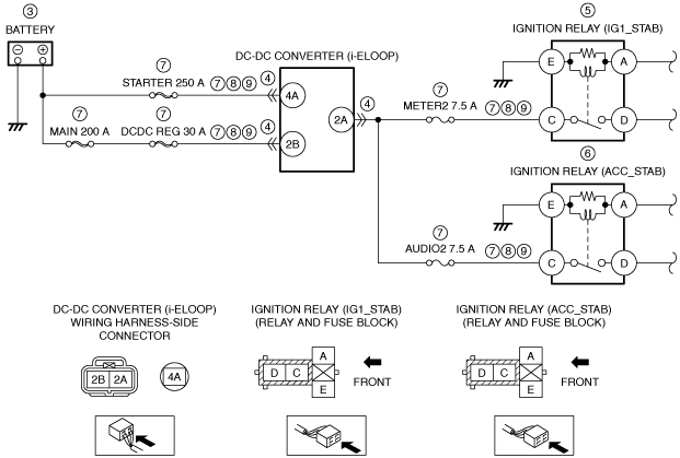
• Refer to the wiring diagram and verify whether or not there is a common connector between the following terminals:
-
― Battery positive terminal—DC-DC converter (i-ELOOP) terminal 4A
― Battery positive terminal—DC-DC converter (i-ELOOP) terminal 2B
― DC-DC converter (i-ELOOP) terminal 2A—Ignition relay (IG1_STAB) terminal C
― DC-DC converter (i-ELOOP) terminal 2A—Ignition relay (ACC_STAB) terminal C
If there is a common connector:
-
― Determine the malfunctioning part by inspecting the common connector and the terminal for corrosion, damage, or pin disconnection, and the common wiring harness for a short to ground.
― Repair or replace the malfunctioning part.
If there is no common connector:
-
― Repair or replace the wiring harness which has a short to ground.
― Replace the malfunctioning fuse.
If the fuse is damaged:
• Replace the malfunctioning fuse.
Go to Step 11.
|
|
8
|
INSPECT DC-DC CONVERTER (i-ELOOP) CIRCUIT FOR SHORT TO GROUND
• Ignition relay (IG1_STAB) and ignition relay (ACC_STAB) are removed.
• Verify that the DC-DC converter (i-ELOOP) connector is disconnected.
• Inspect for continuity between the following terminals (wiring harness-side) and body ground:
-
― DC-DC converter (i-ELOOP) terminal 4A
― DC-DC converter (i-ELOOP) terminal 2B
― DC-DC converter (i-ELOOP) terminal 2A
• Is there continuity?
|
Yes
|
Refer to the wiring diagram and verify whether or not there is a common connector between the following terminals:
• Battery positive terminal—DC-DC converter (i-ELOOP) terminal 4A
• Battery positive terminal—DC-DC converter (i-ELOOP) terminal 2B
• DC-DC converter (i-ELOOP) terminal 2A—Ignition relay (IG1_STAB) terminal C
• DC-DC converter (i-ELOOP) terminal 2A—Ignition relay (ACC_STAB) terminal C
If there is a common connector:
• Determine the malfunctioning part by inspecting the common connector and the terminal for corrosion, damage, or pin disconnection, and the common wiring harness for a short to ground.
• Repair or replace the malfunctioning part.
If there is no common connector:
• Repair or replace the wiring harness which has a short to ground.
Go to Step 11.
|
|
No
|
Go to the next step.
|
|
9
|
INSPECT DC-DC CONVERTER (i-ELOOP) CIRCUIT FOR OPEN CIRCUIT
• Ignition relay (IG1_STAB) and ignition relay (ACC_STAB) are removed.
• Verify that the DC-DC converter (i-ELOOP) connector is disconnected.
• Inspect for continuity between the following terminals (wiring harness-side):
-
― Battery positive terminal—DC-DC converter (i-ELOOP) terminal 4A
― Battery positive terminal—DC-DC converter (i-ELOOP) terminal 2B
― DC-DC converter (i-ELOOP) terminal 2A—Ignition relay (IG1_STAB) terminal C
― DC-DC converter (i-ELOOP) terminal 2A—Ignition relay (ACC_STAB) terminal C
• Is there continuity?
|
Yes
|
Go to the next step.
|
|
No
|
Refer to the wiring diagram and verify whether or not there is a common connector between the following terminals:
• Battery positive terminal—DC-DC converter (i-ELOOP) terminal 4A
• Battery positive terminal—DC-DC converter (i-ELOOP) terminal 2B
• DC-DC converter (i-ELOOP) terminal 2A—Ignition relay (IG1_STAB) terminal C
• DC-DC converter (i-ELOOP) terminal 2A—Ignition relay (ACC_STAB) terminal C
If there is a common connector:
• Determine the malfunctioning part by inspecting the common connector and the terminal for corrosion, damage, or pin disconnection, and the common wiring harness for an open circuit.
• Repair or replace the malfunctioning part.
If there is no common connector:
• Repair or replace the wiring harness which has an open circuit.
Go to Step 11.
|
|
10
|
INSPECT GENERATOR
• Is there any malfunction?
|
Yes
|
Replace the generator, then go to the next step.
|
|
No
|
Go to the next step.
|
|
11
|
VERIFY DTC TROUBLESHOOTING COMPLETED
• Always reconnect all disconnected connectors.
• Reinstall the service plug.
• Reconnect the negative battery cable.
• Clear the DTC for the DC-DC converter (i-ELOOP) using the M-MDS.
• Switch the ignition off.
• Switch the ignition ON (engine off) and wait for 5 s or more.
• Retrieve the DC-DC converter (i-ELOOP) DTCs using the M-MDS.
• Is the same DTC present?
|
Yes
|
Repeat the inspection from Step 1.
• If the malfunction recurs, replace the DC-DC converter (i-ELOOP).
Go to the next step.
|
|
No
|
Go to the next step.
|
|
12
|
VERIFY IF OTHER DTCs DISPLAYED
• Are any other DTCs displayed?
|
Yes
|
Repair or replace the malfunctioning part according to the applicable DTC troubleshooting.
|
|
No
|
DTC troubleshooting completed.
|