DTC U2013:13 [INSTRUMENT CLUSTER]


id0902e8016600

Description

Cluster switch circuit malfunction

Detection condition
•  Instrument cluster detects an open circuit in the cluster switch circuit for 5 s or more with the ignition switched ON (engine off or on).
Fail-safe function
Not applicable
Possible cause
•  Cluster switch connector or terminal malfunction
•  Instrument cluster connector or terminal malfunction
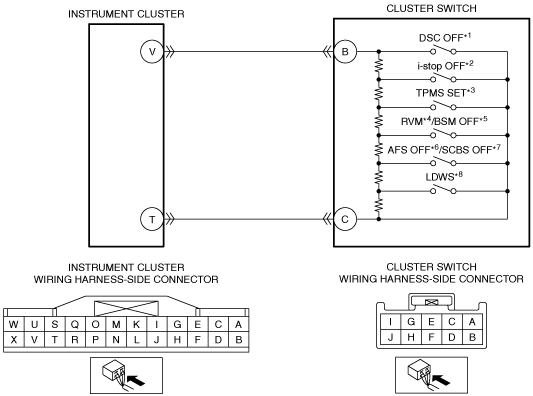
•  Open circuit in wiring harness between the following terminals:
―  Instrument cluster terminal V—Cluster switch terminal B
―  Instrument cluster terminal T—Cluster switch terminal C
•  Cluster switch malfunction
•  Instrument cluster malfunction

*1  :With DSC
*2  :With i-stop system
*3  :With tire pressure monitoring system (TPMS)
*4  :With rear vehicle monitoring system
*5  :With blind spot monitoring (BSM) system
*6  :With AFS
*7  :Without AFS, with smart city brake support (SCBS), L.H.D.
*8  :With lane departure warning system (LDWS)

Diagnostic Procedure

Step

Inspection

Action

1
INSPECT CLUSTER SWITCH CONNECTOR CONDITION
•  Switch the ignition off.
•  Disconnect the cluster switch connector.
•  Inspect the connector engagement and connection condition and inspect the terminals for damage, deformation, corrosion, or disconnection.
•  Is the connector normal?
Yes
Go to the next step.
No
Repair or replace the connector, then go to Step 5.
2
INSPECT INSTRUMENT CLUSTER CONNECTOR CONDITION
•  Disconnect the instrument cluster connector.
•  Inspect the connector engagement and connection condition and inspect the terminals for damage, deformation, corrosion, or disconnection.
•  Is the connector normal?
Yes
Go to the next step.
No
Repair or replace the connector, then go to Step 5.
3
INSPECT FOR OPEN CIRCUIT IN CLUSTER SWITCH CIRCUIT
•  Verify that the cluster switch and instrument cluster connectors are disconnected.
•  Inspect for continuity between the following terminals (wiring harness-side):
―  Instrument cluster terminal V—Cluster switch terminal B
―  Instrument cluster terminal T—Cluster switch terminal C
•  Is there continuity?
Yes
Go to the next step.
No
Refer to the wiring diagram and verify whether or not there is a common connector between the following terminals:
•  Instrument cluster terminal V—Cluster switch terminal B
•  Instrument cluster terminal T—Cluster switch terminal C
If there is a common connector:
•  Determine the malfunctioning part by inspecting the common connector and the terminal for corrosion, damage, or pin disconnection, and the common wiring harness for an open circuit.
•  Repair or replace the malfunctioning part.
If there is no common connector:
•  Repair or replace the wiring harness which has an open circuit.
Go to Step 5.
4
INSPECT CLUSTER SWITCH
•  Is the cluster switch normal?
Yes
Go to the next step.
No
Replace the cluster switch, then go to the next step.
5
VERIFY THAT REPAIRS HAVE BEEN COMPLETED
•  Always reconnect all disconnected connectors.
•  Clear the DTC for the instrument cluster using the M-MDS.
•  Switch the ignition ON (engine off or on) and wait for 5 s or more.
•  Retrieve the instrument cluster DTCs using the M-MDS.
•  Is the same DTC displayed?
Yes
Repeat the inspection from Step 1.
•  If the malfunction recurs, replace the instrument cluster.
Go to the next step.
No
Go to the next step.
6
VERIFY IF OTHER DTCs DISPLAYED
•  Are any other DTCs displayed?
Yes
Repair or replace the malfunctioning part according to the applicable DTC troubleshooting.
No
DTC troubleshooting completed.