 |
ac5uuw00001198
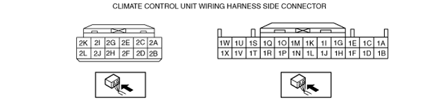
CLIMATE CONTROL UNIT INSPECTION [FULL-AUTO AIR CONDITIONER]
id0740a1802200
Dual Type
1. Disconnect the negative battery cable. (See NEGATIVE BATTERY CABLE DISCONNECTION/CONNECTION [SKYACTIV-D 2.2].)(See NEGATIVE BATTERY CABLE DISCONNECTION/CONNECTION [SKYACTIV-G 1.5, SKYACTIV-G 2.0, SKYACTIV-G 2.5].)(See NEGATIVE BATTERY CABLE DISCONNECTION/CONNECTION [MZR 1.6].)(See NEGATIVE BATTERY CABLE DISCONNECTION/CONNECTION [SKYACTIV-D 1.5].)
2. Remove the following parts:
3. Remove the climate control unit with the connector connected. (See CLIMATE CONTROL UNIT REMOVAL/INSTALLATION [FULL-AUTO AIR CONDITIONER].)
4. Connect the negative battery cable.
5. Switch the ignition ON (engine off or on).
6. Connect the negative (-) lead of the tester to body ground.
7. Insert the positive (+) lead of the tester into each climate control unit terminal and measure the voltage according to the terminal voltage table.
ac5uuw00001198
|
Terminal voltage table (reference)
|
Terminal |
Signal name |
Connected to |
Measurement condition |
Voltage (V) |
Inspection item (s) |
|
|---|---|---|---|---|---|---|
|
1A
|
GND
|
Body ground
|
Under any condition
|
1.0 or less
|
• Related wiring harness
|
|
|
1B
|
B+
|
ROOM 15 A fuse
|
Under any condition
|
B+
|
• Related wiring harness
• ROOM 15 A fuse
|
|
|
1C
|
—
|
—
|
—
|
—
|
—
|
|
|
1D
|
IG1
|
Ignition relay (with i-stop)
C/U IG1 15 A fuse (without i-stop)
|
Switch the ignition ON (engine off or on)
|
B+
|
• Related wiring harness
• Ignition relay
• C/U IG1 15 A fuse (without i-stop)
|
|
|
Switch the ignition off
|
1.0 or less
|
|||||
|
1E
|
Blower fan speed control
|
Blower fan controller
|
• Related wiring harness
• Blower fan controller
|
|||
|
1F
|
IG2
|
Front body control module (FBCM)
|
Switch the ignition ON (engine off or on)
|
B+
|
• Related wiring harness
• Front body control module (FBCM)
|
|
|
Switch the ignition off
|
1.0 or less
|
|||||
|
1G
|
—
|
—
|
—
|
—
|
—
|
|
|
1H
|
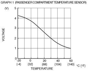
Cabin temperature sensor input
|
Cabin temperature sensor
|
Compared with temperature detected by cabin temperature sensor
|
Refer to graph 1
|
• Related wiring harness
• Cabin temperature sensor
• Climate control unit: terminal voltage (1N)
|
|
|
1I
|
—
|
—
|
—
|
—
|
—
|
|
|
1J
|
Sensor GND
|
• Driver-side air mix actuator
• Passenger-side air mix actuator
• Airflow mode actuator
• Evaporator temperature sensor
• Cabin temperature sensor
|
Under any condition
|
1.0 or less
|
• Related wiring harness
• Climate control unit: terminal voltage (1N)
|
|
|
1K
|
—
|
—
|
—
|
—
|
—
|
|
|
1L
|
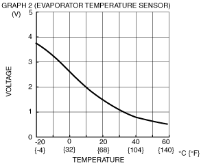
Evaporator temperature sensor input
|
Evaporator temperature sensor
|
Compared with temperature detected by evaporator temperature sensor
|
Refer to graph 2
|
• Related wiring harness
• Evaporator temperature sensor
• Climate control unit: terminal voltage (1N)
|
|
|
1M
|
Solar radiation sensor (LH) input
|
Solar radiation sensor
|
Sunlight shined directly on solar radiation sensor
|
4
|
• Related wiring harness
• Climate control unit: terminal voltage (1N)
• Solar radiation sensor
|
|
|
Blocking light to solar radiation sensor
|
1.0 or less
|
|||||
|
1N
|
+5V
|
• Driver-side air mix actuator
• Passenger-side air mix actuator
• Airflow mode actuator
• Solar radiation sensor
|
Under any condition
|
5
|
• Related wiring harness
• Driver-side air mix actuator
• Passenger-side air mix actuator
• Airflow mode actuator
• Solar radiation sensor
• Climate control unit: terminal voltage (1J)
|
|
|
1O
|
Solar radiation sensor (RH) input
|
Solar radiation sensor
|
Sunlight shined directly on solar radiation sensor
|
4
|
• Related wiring harness
• Climate control unit: terminal voltage (1N)
• Solar radiation sensor
|
|
|
Blocking light to solar radiation sensor
|
1.0 or less
|
|||||
|
1P
|
—
|
—
|
—
|
—
|
—
|
|
|
1Q
|
—
|
—
|
—
|
—
|
—
|
|
|
1R
|
—
|
—
|
—
|
—
|
—
|
|
|
1S
|
MS_CAN_H
|
CAN related module
|
Because this terminal is for communication, integrity determination by terminal voltage is not possible.
|
• Related wiring harness
|
||
|
1T
|
—
|
—
|
—
|
—
|
—
|
|
|
1U
|
MS_CAN_L
|
CAN related module
|
Because this terminal is for communication, integrity determination by terminal voltage is not possible.
|
• Related wiring harness
|
||
|
1V
|
—
|
—
|
—
|
—
|
—
|
|
|
1W
|
—
|
—
|
—
|
—
|
—
|
|
|
1X
|
—
|
—
|
—
|
—
|
—
|
|
|
2A
|
Potentiometer input
|
Airflow mode actuator
|
VENT
|
4.3 or more
|
• Related wiring harness
• Airflow mode actuator
• Climate control unit: terminal voltage (1N)
|
|
|
BI-LEVEL
|
3.4
|
|||||
|
HEAT
|
2.5
|
|||||
|
HEAT/DEF
|
1.6
|
|||||
|
DEFROSTER
|
0.7 or less
|
|||||
|
2B
|
Motor operation (COLD)
|
• Driver-side air mix actuator (L.H.D.)
• Passenger-side air mix actuator (R.H.D.)
|
Moving towards HOT
|
1.0 or less
|
• Related wiring harness
• Driver-side air mix actuator (L.H.D.)
• Passenger-side air mix actuator (R.H.D.)
|
|
|
Moving towards COLD
|
B+
|
|||||
|
2C
|
—
|
—
|
—
|
—
|
—
|
|
|
2D
|
Motor operation (HOT)
|
• Driver-side air mix actuator (L.H.D.)
• Passenger-side air mix actuator (R.H.D.)
|
Moving towards HOT
|
B+
|
• Related wiring harness
• Driver-side air mix actuator (L.H.D.)
• Passenger-side air mix actuator (R.H.D.)
|
|
|
Moving towards COLD
|
1.0 or less
|
|||||
|
2E
|
Potentiometer input
|
• Passenger-side air mix actuator (L.H.D.)
• Driver-side air mix actuator (R.H.D.)
|
Set temperature at MAX HOT
|
4.3 or more
|
• Related wiring harness
• Passenger-side air mix actuator (L.H.D.)
• Driver-side air mix actuator (R.H.D.)
|
|
|
Set temperature at MAX COLD
|
1.0 or less
|
|||||
|
2F
|
Motor operation (HOT)
|
• Passenger-side air mix actuator (L.H.D.)
• Driver-side air mix actuator (R.H.D.)
|
Moving towards HOT
|
B+
|
• Related wiring harness
• Passenger-side air mix actuator (L.H.D.)
• Driver-side air mix actuator (R.H.D.)
|
|
|
Moving towards COLD
|
1.0 or less
|
|||||
|
2G
|
Potentiometer input
|
• Driver-side air mix actuator (L.H.D.)
• Passenger-side air mix actuator (R.H.D.)
|
Set temperature at MAX HOT
|
4.3 or more
|
• Related wiring harness
• Driver-side air mix actuator (L.H.D.)
• Passenger-side air mix actuator (R.H.D.)
• Climate control unit: terminal voltage (1N)
|
|
|
Set temperature at MAX COLD
|
1.0 or less
|
|||||
|
2H
|
Motor operation (COLD)
|
• Passenger-side air mix actuator (L.H.D.)
• Driver-side air mix actuator (R.H.D.)
|
Moving towards HOT
|
1.0 or less
|
• Related wiring harness
• Passenger-side air mix actuator (L.H.D.)
• Driver-side air mix actuator (R.H.D.)
|
|
|
Moving towards COLD
|
B+
|
|||||
|
2I
|
Motor operation (VENT)
|
Airflow mode actuator
|
Moving towards VENT
|
B+
|
• Related wiring harness
• Airflow mode actuator
|
|
|
Moving towards DEFROSTER
|
1.0 or less
|
|||||
|
2J
|
Motor operation (FRESH)
|
Air intake actuator
|
Moving towards RECIRCULATE
|
1.0 or less
|
• Related wiring harness
• Air intake actuator
|
|
|
Moving towards FRESH
|
B+
|
|||||
|
2K
|
Motor operation (DEFROSTER)
|
Airflow mode actuator
|
Moving towards DEFROSTER
|
B+
|
• Related wiring harness
• Airflow mode actuator
|
|
|
Moving towards VENT
|
1.0 or less
|
|||||
|
2L
|
Motor operation (RECIRCULATE)
|
Air intake actuator
|
Moving towards RECIRCULATE
|
B+
|
• Related wiring harness
• Air intake actuator
|
|
|
Moving towards FRESH
|
1.0 or less
|
|||||
 |
 |
Single Type
1. Disconnect the negative battery cable. (See NEGATIVE BATTERY CABLE DISCONNECTION/CONNECTION [SKYACTIV-G 1.5, SKYACTIV-G 2.0, SKYACTIV-G 2.5].) (See NEGATIVE BATTERY CABLE DISCONNECTION/CONNECTION [MZR 1.6].)
2. Remove the following parts:
3. Remove the climate control unit with the connector connected. (See CLIMATE CONTROL UNIT REMOVAL/INSTALLATION [FULL-AUTO AIR CONDITIONER].)
4. Connect the negative battery cable.
5. Switch the ignition ON (engine off or on).
6. Connect the negative (-) lead of the tester to body ground.
7. Insert the positive (+) lead of the tester into each climate control unit terminal and measure the voltage according to the terminal voltage table.
am3uuw00010220
|
Terminal voltage table (reference)
|
Terminal |
Signal name |
Connected to |
Measurement condition |
Voltage (V) |
Inspection item (s) |
|
|---|---|---|---|---|---|---|
|
A
|
—
|
—
|
—
|
—
|
—
|
|
|
B
|
MS_CAN_L
|
CAN related module
|
Because this terminal is for communication, integrity determination by terminal voltage is not possible.
|
• Related wiring harness
|
||
|
C
|
GND
|
Body ground
|
Under any condition
|
1.0 or less
|
• Related wiring harness
|
|
|
D
|
MS_CAN_H
|
CAN related module
|
Because this terminal is for communication, integrity determination by terminal voltage is not possible.
|
• Related wiring harness
|
||
|
E
|
Sensor GND
|
• Air mix actuator
• Airflow mode actuator
• Passenger compartment temperature sensor
• Evaporator temperature sensor
|
Under any condition
|
1.0 or less
|
• Related wiring harness
• Climate control unit: terminal voltage (H)
|
|
|
F
|
Passenger compartment temperature sensor input
|
Passenger compartment temperature sensor
|
Compared with temperature detected by passenger compartment temperature sensor
|
Refer to graph 1
|
• Related wiring harness
• Passenger compartment temperature sensor
• Climate control unit: terminal voltage (H)
|
|
|
G
|
Potentiometer input
|
Passenger-side air mix actuator
|
Set temperature at MAX HOT
|
4.3 or more
|
• Related wiring harness
• Passenger-side air mix actuator
• Climate control unit: terminal voltage (H)
|
|
|
Set temperature at MAX COLD
|
1.0 or less
|
|||||
|
H
|
+5V
|
• Air mix actuator
• Airflow mode actuator
• Solar radiation sensor
|
Under any condition
|
5
|
• Related wiring harness
• Air mix actuator
• Airflow mode actuator
• Solar radiation sensor
• Climate control unit: terminal voltage (E)
|
|
|
I
|
Potentiometer input
|
Airflow mode actuator
|
VENT
|
4.3 or more
|
• Related wiring harness
• Airflow mode actuator
• Climate control unit: terminal voltage (H)
|
|
|
BI-LEVEL
|
3.4
|
|||||
|
HEAT
|
2.5
|
|||||
|
HEAT/DEF
|
1.6
|
|||||
|
DEFROSTER
|
0.7 or less
|
|||||
|
J
|
Evaporator temperature sensor input
|
Evaporator temperature sensor
|
Compared with temperature detected by evaporator temperature sensor
|
Refer to graph 2
|
• Related wiring harness
• Evaporator temperature sensor
• Climate control unit: terminal voltage (H)
|
|
|
K
|
Solar radiation sensor (RH) input
|
Solar radiation sensor
|
Sunlight shined directly on solar radiation sensor
|
4
|
• Related wiring harness
• Climate control unit: terminal voltage (H)
• Solar radiation sensor
|
|
|
Blocking light to solar radiation sensor
|
1.0 or less
|
|||||
|
L
|
B+
|
ROOM 15 A fuse
|
Under any condition
|
B+
|
• Related wiring harness
• ROOM 15 A fuse
|
|
|
M
|
Solar radiation sensor (LH) input
|
Solar radiation sensor
|
Sunlight shined directly on solar radiation sensor
|
4
|
• Related wiring harness
• Climate control unit: terminal voltage (H)
• Solar radiation sensor
|
|
|
Blocking light to solar radiation sensor
|
1.0 or less
|
|||||
|
N
|
IG2
|
Front body control module (FBCM)
|
Switch the ignition ON (engine off or on)
|
B+
|
• Related wiring harness
• Front body control module (FBCM)
|
|
|
Switch the ignition off
|
1.0 or less
|
|||||
|
O
|
—
|
—
|
—
|
—
|
—
|
|
|
P
|
—
|
—
|
—
|
—
|
—
|
|
|
Q
|
Blower fan speed control
|
Blower fan controller
|
• Related wiring harness
• Blower fan controller
|
|||
|
R
|
—
|
—
|
—
|
—
|
—
|
|
|
S
|
Motor operation (RECIRCULATE)
|
Air intake actuator
|
Moving towards RECIRCULATE
|
B+
|
• Related wiring harness
• Air intake actuator
|
|
|
Moving towards FRESH
|
1.0 or less
|
|||||
|
T
|
Motor operation (VENT)
|
Airflow mode actuator
|
Moving towards VENT
|
B+
|
• Related wiring harness
• Airflow mode actuator
|
|
|
Moving towards DEFROSTER
|
1.0 or less
|
|||||
|
U
|
Motor operation (FRESH)
|
Air intake actuator
|
Moving towards RECIRCULATE
|
1.0 or less
|
• Related wiring harness
• Air intake actuator
|
|
|
Moving towards FRESH
|
B+
|
|||||
|
V
|
Motor operation (DEFROSTER)
|
Airflow mode actuator
|
Moving towards DEFROSTER
|
B+
|
• Related wiring harness
• Airflow mode actuator
|
|
|
Moving towards VENT
|
1.0 or less
|
|||||
|
W
|
Motor operation (COLD)
|
Air mix actuator
|
Moving towards HOT
|
1.0 or less
|
• Related wiring harness
• Air mix actuator
|
|
|
Moving towards COLD
|
B+
|
|||||
|
X
|
Motor operation (HOT)
|
Air mix actuator
|
Moving towards HOT
|
B+
|
• Related wiring harness
• Air mix actuator
|
|
|
Moving towards COLD
|
1.0 or less
|
|||||
|
|
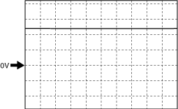
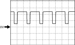
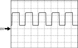
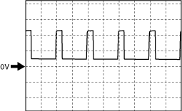
Blower Fan Speed Control Signal
Fan stopped
aaxjjw00019786
|
Manual 1st
aaxjjw00019787
|
Manual 3rd
aaxjjw00019788
|
Manual 7th
aaxjjw00019789
|