 |
ac5uuw00001232
CLIMATE CONTROL UNIT INSPECTION [MANUAL AIR CONDITIONER]
id0740a2802200
1. Disconnect the negative battery cable. (See NEGATIVE BATTERY CABLE DISCONNECTION/CONNECTION [SKYACTIV-D 2.2].)(See NEGATIVE BATTERY CABLE DISCONNECTION/CONNECTION [SKYACTIV-G 1.5, SKYACTIV-G 2.0, SKYACTIV-G 2.5].)(See NEGATIVE BATTERY CABLE DISCONNECTION/CONNECTION [MZR 1.6].)(See NEGATIVE BATTERY CABLE DISCONNECTION/CONNECTION [SKYACTIV-D 1.5].)
2. Remove the following parts:
3. Remove the climate control unit with the connector connected. (See CLIMATE CONTROL UNIT REMOVAL/INSTALLATION [MANUAL AIR CONDITIONER].)
4. Switch the ignition ON (engine off or on).
5. Connect the negative (-) lead of the tester to the body ground.
6. By inserting the positive (+) lead of the tester into the climate control unit connector, measure the voltage according to the terminal voltage table.
ac5uuw00001232
|
Terminal Voltage Table (7-Speed Type Airflow Volume Control Dial) (Reference)
|
Terminal |
Signal name |
Connected to |
Measurement condition |
Voltage (V) |
Inspection item(s) |
|
|---|---|---|---|---|---|---|
|
A
|
TNS signal
|
Front body control module (FBCM)
|
TNS OFF
|
1.0 or less
|
• Related wiring harness
• Front body control module (FBCM)
|
|
|
TNS ON
|
B+
|
|||||
|
B
|
Illumination (-)
|
Instrument cluster
|
Headlight ON and panel light control MAX
|
2.0
|
• Instrument cluster
• Related wiring harness
|
|
|
Headlight ON and panel light control MIN
|
9.65
|
|||||
|
C
|
Motor operation (RECIRCULATE)
|
Air intake actuator
|
Switched to RECIRCULATE
|
B+
|
• Related wiring harness
• Air intake actuator
|
|
|
Switched to FRESH
|
1.0 or less
|
|||||
|
D
|
Ground
|
Body ground
|
Under any condition
|
1.0 or less
|
• Related wiring harness
|
|
|
E
|
Motor operation (FRESH)
|
Air intake actuator
|
Switched to RECIRCULATE
|
1.0 or less
|
• Related wiring harness
• Air intake actuator
|
|
|
Switched to FRESH
|
B+
|
|||||
|
F
|
Sensor GND
|
Evaporator temperature sensor
|
Under any condition
|
1.0 or less
|
• Related wiring harness
• Climate control unit: terminal voltage (H)
|
|
|
G
|
—
|
—
|
—
|
—
|
—
|
|
|
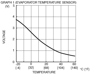
H*1
|
Evaporator temperature sensor input
|
Evaporator temperature sensor
|
Compared with temperature detected by evaporator temperature sensor
|
Refer to graph 1
|
• Related wiring harness
• Evaporator temperature sensor
• Climate control unit: terminal voltage (F)
|
|
|
I
|
Blower fan speed control
|
Blower fan controller
|
• Related wiring harness
• Blower fan controller
|
|||
|
J
|
B+
|
ROOM 15 A fuse
|
Under any condition
|
B+
|
• Related wiring harness
• ROOM 15 A fuse
|
|
|
K
|
LIN
|
Front body control module (FBCM)
|
Because this terminal is for communication, good/no good judgment by terminal voltage is not possible.
|
• Related wiring harness
• Front body control module (FBCM)
|
||
|
L
|
IG2
|
Front body control module (FBCM)
|
Switch the ignition to ON
|
B+
|
• Related wiring harness
• Front body control module (FBCM)
|
|
|
Switch the ignition off
|
1.0 or less
|
|||||
 |
Terminal Voltage Table (4-Speed Type Airflow Volume Control Dial) (Reference)
|
Terminal |
Signal name |
Connected to |
Measurement condition |
Voltage (V) |
Inspection item(s) |
|---|---|---|---|---|---|
|
A
|
TNS signal
|
Front body control module (FBCM)
|
TNS OFF
|
1.0 or less
|
• Related wiring harness
• Front body control module (FBCM)
|
|
TNS ON
|
B+
|
||||
|
B
|
Illumination (-)
|
Instrument cluster
|
Headlight ON and panel light control MAX
|
2.0
|
• Instrument cluster
• Related wiring harness
|
|
Headlight ON and panel light control MIN
|
9.65
|
||||
|
C
|
Motor operation (RECIRCULATE)
|
Air intake actuator
|
Switched to RECIRCULATE
|
B+
|
• Related wiring harness
• Air intake actuator
|
|
Switched to FRESH
|
1.0 or less
|
||||
|
D
|
Ground
|
Body ground
|
Under any condition
|
1.0 or less
|
• Related wiring harness
|
|
E
|
Motor operation (FRESH)
|
Air intake actuator
|
Switched to RECIRCULATE
|
1.0 or less
|
• Related wiring harness
• Air intake actuator
|
|
Switched to FRESH
|
B+
|
||||
|
F
|
Sensor GND
|
Evaporator temperature sensor
|
Under any condition
|
1.0 or less
|
• Related wiring harness
• Evaporator temperature sensor
|
|
G
|
Blower fan ON/OFF signal
|
Fan switch
|
Fan stopped
|
B+
|
• Related wiring harness
• Resistor
• Fan switch terminal voltage (D)
|
|
Fan on
|
1.0 or less
|
||||
|
H
|
Evaporator temperature sensor input
|
Evaporator temperature sensor
|
Compared with temperature detected by evaporator temperature sensor
|
Refer to graph 1
|
• Related wiring harness
• Evaporator temperature sensor
• Climate control unit: terminal voltage (F)
|
|
I
|
Blower fan position signal
|
Fan switch
|
3rd, 4th
|
1.0 or less
|
• Related wiring harness
• Resistor
• Fan switch terminal voltage (D)
|
|
off, 1st, 2nd
|
B+
|
||||
|
J
|
B+
|
ROOM 15 A fuse
|
Under any condition
|
B+
|
• Related wiring harness
• ROOM 15 A fuse
|
|
K
|
LIN
|
Front body control module (FBCM)
|
Because this terminal is for communication, good/no good judgment by terminal voltage is not possible.
|
• Related wiring harness
• Front body control module (FBCM)
|
|
|
L
|
IG2
|
Front body control module (FBCM)
|
Switch the ignition ON (engine off or on)
|
B+
|
• Related wiring harness
• Front body control module (FBCM)
|
|
Switch the ignition off
|
1.0 or less
|
||||
|
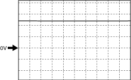
Blower Fan Speed Control Signal
Fan stopped
aaxjjw00019786
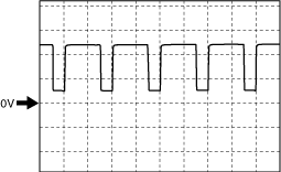
|
Manual 1st
aaxjjw00019787
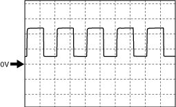
|
Manual 3rd
aaxjjw00019788
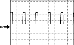
|
Manual 7th
aaxjjw00019789
|