|
1
|
VERIFY TCM DTCs
• Retrieve the TCM DTCs using the M-MDS.
• Are any DTCs displayed?
|
Yes
|
Repair or replace the malfunctioning part according to the applicable DTC troubleshooting.
|
|
No
|
Go to the next step.
|
|
2
|
VERIFY PCM DTCs
• Retrieve the PCM DTCs using the M-MDS.
• Are any DTCs displayed?
|
Yes
|
Repair or replace the malfunctioning part according to the applicable DTC troubleshooting.
|
|
No
|
Go to the next step.
|
|
3
|
INSPECT TCM CONNECTOR CONDITION
• Switch the ignition off.
• Disconnect the negative battery cable.
• Disconnect the TCM connector.
• Inspect the connector engagement and connection condition and inspect the terminals for damage, deformation, corrosion, or disconnection.
• Is the connector normal?
|
Yes
|
Go to the next step.
|
|
No
|
Repair or replace the connector, then go to Step 9.
|
|
4
|
INSPECT PCM CONNECTOR CONDITION
• Disconnect the PCM connector.
• Inspect the connector engagement and connection condition and inspect the terminals for damage, deformation, corrosion, or disconnection.
• Is the connector normal?
|
Yes
|
Go to the next step.
|
|
No
|
Repair or replace the connector, then go to Step 9.
|
|
5
|
INSPECT START STOP UNIT CONNECTOR CONDITION
• Disconnect the start stop unit connector.
• Inspect the connector engagement and connection condition and inspect the terminals for damage, deformation, corrosion, or disconnection.
• Is the connector normal?
|
Yes
|
Go to the next step.
|
|
No
|
Repair or replace the connector, then go to Step 9.
|
|
6
|
INSPECT FOR SHORT TO POWER SUPPLY IN TRANSAXLE RANGE SENSOR CIRCUIT
• Always reconnect all disconnected connectors.
• Reconnect the negative battery cable.
• Operate the selector lever to P or N position.
• Measure the voltage at the start stop unit terminal 1F (wiring harness-side).
• Is the voltage 1.0 V or less?
|
Yes
|
Go to the next step.
|
|
No
|
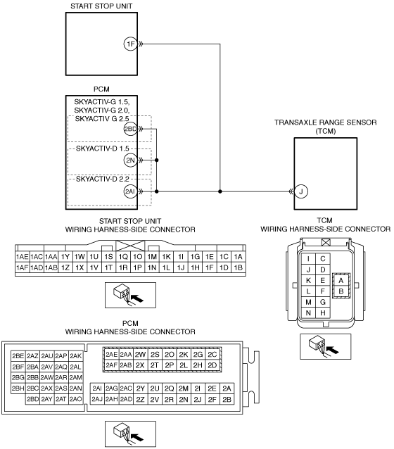
Refer to the wiring diagram and verify whether or not there is a common connector between the following terminals:
• TCM terminal J—PCM terminal 2BD (SKYACTIV-G 1.5, SKYACTIV-G 2.0, SKYACTIV-G 2.5)
• TCM terminal J—PCM terminal 2N (SKYACTIV-D 1.5)
• TCM terminal J—PCM terminal 2AI (SKYACTIV-D 2.2)
• TCM terminal J—Start stop unit terminal 1F
If there is a common connector:
• Determine the malfunctioning part by inspecting the common connector and the terminal for corrosion, damage, or pin disconnection, and the common wiring harness for a short to power supply.
• Repair or replace the malfunctioning part.
If there is no common connector:
• Repair or replace the wiring harness which has a short to power supply.
Go to Step 9.
|
|
7
|
PERFORM DTC INSPECTION AND VERIFY TRANSAXLE RANGE SENSOR MALFUNCTION
• Always reconnect all disconnected connectors.
• Reconnect the negative battery cable.
• Clear the DTC for the start stop unit using the M-MDS.
• Switch the ignition ON (engine off).
• Perform the following work 5 times or more.
-
― Operate the selector lever to P or N position and wait for 1 s or more.
― Operate the selector lever to other than P and N position and wait for 1 s or more.
― Operate the selector lever to P or N position.
• Retrieve the start stop unit DTCs using the M-MDS.
• Is the same DTC displayed?
|
Yes
|
Replace the TCM, then go to the next step.
|
|
No
|
Go to Step 10.
|
|
8
|
PERFORM DTC INSPECTION AND VERIFY PCM MALFUNCTION
• Clear the DTC for the start stop unit using the M-MDS.
• Switch the ignition ON (engine off).
• Perform the following work 5 times or more.
-
― Operate the selector lever to P or N position and wait for 1 s or more.
― Operate the selector lever to other than P and N position and wait for 1 s or more.
― Operate the selector lever to P or N position.
• Retrieve the start stop unit DTCs using the M-MDS.
• Is the same DTC displayed?
|
Yes
|
Replace the PCM, then go to the next step.
|
|
No
|
Go to Step 10.
|
|
9
|
VERIFY THAT REPAIRS HAVE BEEN COMPLETED
• Always reconnect all disconnected connectors.
• Reconnect the negative battery cable.
• Clear the DTC for the start stop unit using the M-MDS.
• Switch the ignition ON (engine off).
• Perform the following work 5 times or more.
-
― Operate the selector lever to P or N position and wait for 1 s or more.
― Operate the selector lever to other than P and N position and wait for 1 s or more.
― Operate the selector lever to P or N position.
• Retrieve the start stop unit DTCs using the M-MDS.
• Is the same DTC displayed?
|
Yes
|
Repeat the inspection from Step 1.
• If the malfunction recurs, replace the start stop unit.
Go to the next step.
|
|
No
|
Go to the next step.
|
|
10
|
VERIFY IF OTHER DTCs DISPLAYED
• Are any other DTCs displayed?
|
Yes
|
Repair or replace the malfunctioning part according to the applicable DTC troubleshooting.
|
|
No
|
DTC troubleshooting completed.
|