 |
am3zzw00014964
ENGINE REMOVAL/INSTALLATION [SKYACTIV-G 1.5, SKYACTIV-G 2.0, SKYACTIV-G 2.5]
id0110h6800400
1. Disconnect the negative battery cable. (See NEGATIVE BATTERY CABLE DISCONNECTION/CONNECTION [SKYACTIV-G 1.5, SKYACTIV-G 2.0, SKYACTIV-G 2.5].)
2. Remove the plug hole plate. (See PLUG HOLE PLATE REMOVAL/INSTALLATION [SKYACTIV-G 1.5, SKYACTIV-G 2.0, SKYACTIV-G 2.5].)
3. Remove the air cleaner, air hose and fresh air duct as a single unit. (See INTAKE-AIR SYSTEM REMOVAL/INSTALLATION [SKYACTIV-G 1.5, SKYACTIV-G 2.0, SKYACTIV-G 2.5].)
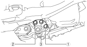
4. Remove the bolts, nut and connector shown in the figure, and set the wiring harness aside.
am3zzw00014964
|
5. Remove the battery tray and PCM component. (See BATTERY REMOVAL/INSTALLATION [SKYACTIV-G 1.5, SKYACTIV-G 2.0, SKYACTIV-G 2.5].)
6. Remove the front under cover No.1 and No.2. (See FRONT UNDER COVER No.1 REMOVAL/INSTALLATION.) (See FRONT UNDER COVER No.2 REMOVAL/INSTALLATION.)
7. Remove the splash shield. (See SPLASH SHIELD REMOVAL/INSTALLATION.)
8. Drain the engine coolant. (See ENGINE COOLANT REPLACEMENT [SKYACTIV-G 1.5, SKYACTIV-G 2.0, SKYACTIV-G 2.5].)
9. Drain the transaxle oil (MTX) or ATF (ATX).
10. Remove the front wheels and tires. (See GENERAL PROCEDURES (SUSPENSION).)
11. Disconnect the selector cable. (ATX) (See AUTOMATIC TRANSAXLE SHIFT MECHANISM REMOVAL/INSTALLATION.)
12. Disconnect the control cable. (MTX) (See MANUAL TRANSAXLE SHIFT MECHANISM REMOVAL/INSTALLATION [C66M-R].) (See MANUAL TRANSAXLE SHIFT MECHANISM REMOVAL/INSTALLATION [F66M-R].)
13. Remove the clutch release cylinder with the pipe still connected. (MTX) (See CLUTCH RELEASE CYLINDER REMOVAL/INSTALLATION [C66M-R].) (See CLUTCH RELEASE CYLINDER REMOVAL/INSTALLATION [F66M-R].)
14. Disconnect the vacuum hose. (See VACUUM HOSE REMOVAL/INSTALLATION.)
15. Disconnect evaporative hose No.1 from the engine side. (See PURGE SOLENOID VALVE REMOVAL/INSTALLATION [SKYACTIV-G 1.5, SKYACTIV-G 2.0, SKYACTIV-G 2.5].)
16. Disconnect the fuel hose from the engine side. (See QUICK RELEASE CONNECTOR REMOVAL/INSTALLATION [SKYACTIV-G 1.5, SKYACTIV-G 2.0, SKYACTIV-G 2.5].)
17. Disconnect the upper radiator hose. (See COOLING FAN MOTOR REMOVAL/INSTALLATION [SKYACTIV-G 1.5, SKYACTIV-G 2.0, SKYACTIV-G 2.5].)
18. Disconnect the heater hose. (See A/C UNIT REMOVAL/INSTALLATION.)
19. Disconnect the lower radiator hose. (See RADIATOR REMOVAL/INSTALLATION [SKYACTIV-G 1.5, SKYACTIV-G 2.0, SKYACTIV-G 2.5].)
20. Remove the generator drive belt. (See DRIVE BELT REMOVAL/INSTALLATION [SKYACTIV-G 1.5, SKYACTIV-G 2.0, SKYACTIV-G 2.5].)
21. Remove the A/C compressor with the cooler hose still connected and secure it using wire or rope so that it is out of the way. (with A/C) (See A/C COMPRESSOR REMOVAL/INSTALLATION [SKYACTIV-G 1.5, SKYACTIV-G 2.0, SKYACTIV-G 2.5].)
22. Remove the TWC installation nuts (exhaust manifold side) and secure the TWC using wire or rope so that it is out of the way. (See EXHAUST SYSTEM REMOVAL/INSTALLATION [SKYACTIV-G 1.5, SKYACTIV-G 2.0, SKYACTIV-G 2.5].)
23. Disconnect the drive shaft from the transaxle side and set the drive shaft out of the way. (See FRONT DRIVE SHAFT REMOVAL/INSTALLATION.)
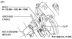
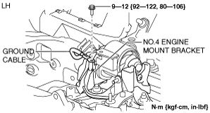
24. Remove the bolt and clips, and set the ground cable aside.
am6zzw00010035
|
am6zzw00010036
|
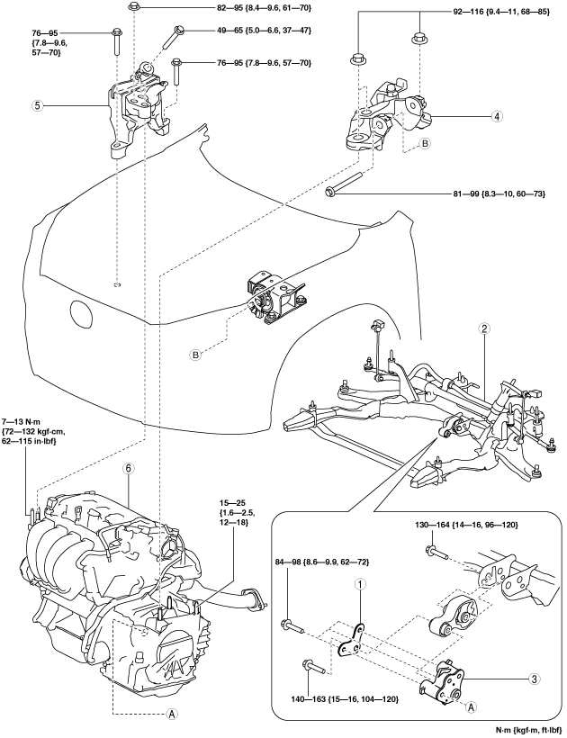
25. Remove in the order indicated in the table.
26. Install in the reverse order of removal.
27. Refill the transaxle oil (MTX) or ATF (ATX).
28. Refill the engine coolant. (See ENGINE COOLANT REPLACEMENT [SKYACTIV-G 1.5, SKYACTIV-G 2.0, SKYACTIV-G 2.5].)
29. Start the engine, and inspect and adjust the following:
No.1 Engine Mount Type A
am3zzw00016082
|
|
1
|
Bracket plate
|
|
2
|
No.1 engine mount bracket
|
|
3
|
No.1 engine mount rubber, front crossmember component
|
|
4
|
No.4 engine mount bracket
|
|
5
|
No.3 engine mount
|
|
6
|
Engine, transaxle
|
No.1 engine mount rubber, front crossmember component removal note (No.1 Engine Mount Type A)
1. Disconnect the service plug. (with i-ELOOP) (See SERVICE PLUG DISCONNECTION/CONNECTION [i-ELOOP].)
2. Disconnect the generator terminal B cable. (with i-ELOOP) (See GENERATOR REMOVAL/INSTALLATION [SKYACTIV-G 1.5, SKYACTIV-G 2.0, SKYACTIV-G 2.5 (WITH i-ELOOP)].)
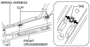
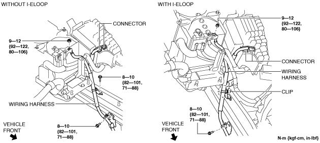
3. Remove the clips shown in the figure and set the wiring harness aside. (with i-ELOOP)
am6zzw00010037
|
4. Loosen the bolts shown in the figure.
am3zzw00016083
|
5. Remove the No.1 engine mount rubber and the front crossmember component as a single unit. (See FRONT CROSSMEMBER REMOVAL/INSTALLATION [SKYACTIV-G 1.5, SKYACTIV-G 2.0, SKYACTIV-G 2.5].)
No.3 engine mount, No.4 engine mount bracket removal note (No.1 Engine Mount Type A)
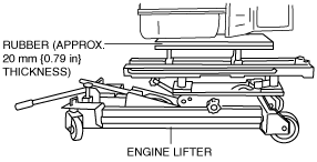
1. Secure the engine and transaxle using a commercially available engine lifter.
am3uuw00008802
|
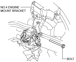
2. Remove the No.4 engine mount bracket.
3. Remove the No.3 engine mount.
Engine mount installation note (No.1 Engine Mount Type A)
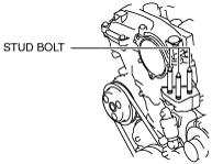
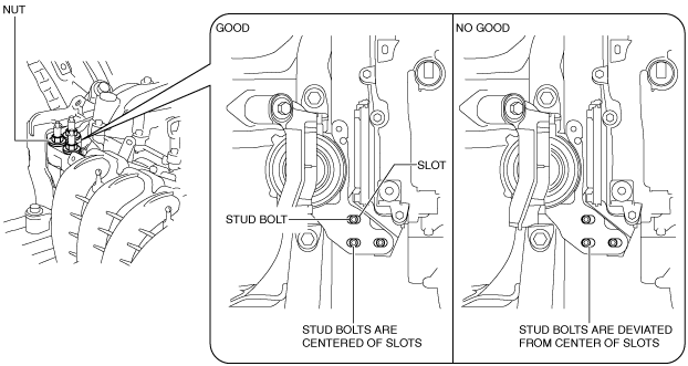
1. Tighten the engine front cover stud bolts.
am3uuw00008803
|
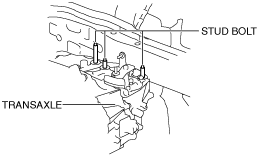
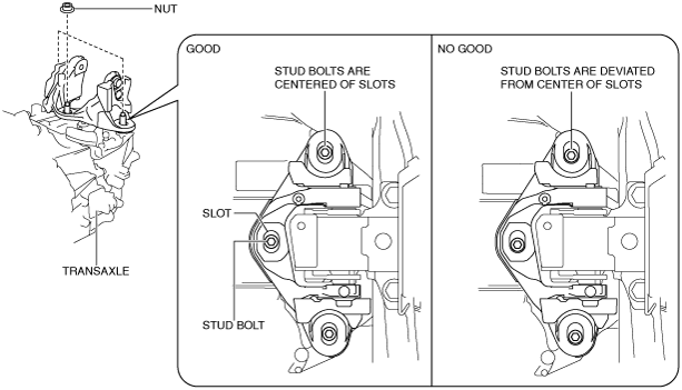
2. Tighten the transaxle stud bolts.
ac5uuw00000612
|
3. Secure the engine and transaxle using a commercially available engine lifter.
am3uuw00008802
|
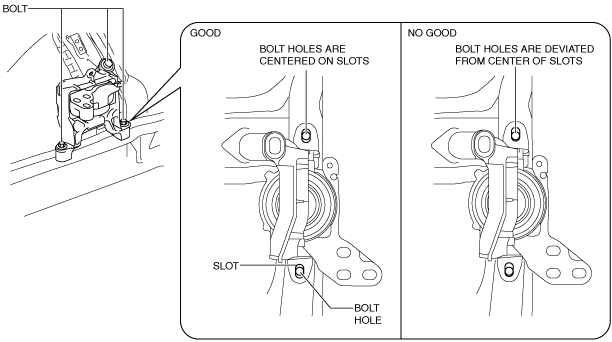
4. Temporarily tighten the No.3 engine mount installation bolts and nuts using the following procedure:
ac5uuw00003037
|
ac5uuw00003038
|
5. Temporarily tighten the No.4 engine mount bracket installation bolt and nuts using the following procedure:
ac5uuw00000615
|
ac5uuw00003039
|
6. Install the No.1 engine mount rubber and the front crossmember component as a single unit. (See FRONT CROSSMEMBER REMOVAL/INSTALLATION [SKYACTIV-G 1.5, SKYACTIV-G 2.0, SKYACTIV-G 2.5].)
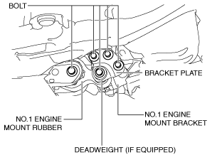
7. Install the following parts and temporarily tighten the bolts shown in the figure.
am3zzw00016084
|
8. Tighten the No.1 engine mount bracket and bracket plate installation bolts in the order shown in the figure.
am3uuw00011891
|
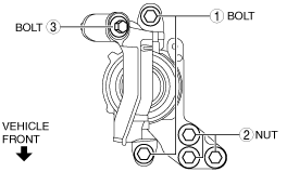
9. Tighten the No.3 engine mount installation bolts and nuts in the order shown in the figure.
am3zzw00014968
|
Tightening torque
|
Installation position |
Tightening torque |
|---|---|
|
1
|
76—95 N·m {7.8—9.6 kgf·m, 57—70 ft·lbf}
|
|
2
|
82—95 N·m {8.4—9.6 kgf·m, 61—70 ft·lbf}
|
|
3
|
49—65 N·m {5.0—6.6 kgf·m, 37—47 ft·lbf}
|
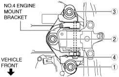
10. Tighten the No.4 engine mount bracket installation bolt and nuts in the order shown in the figure.
am3zzw00014969
|
Tightening torque
|
Installation position |
Tightening torque |
|---|---|
|
1, 2, 3
|
92—116 N·m {9.4—11 kgf·m, 68—85 ft·lbf}
|
|
4
|
81—99 N·m {8.3—10 kgf·m, 60—73 ft·lbf}
|
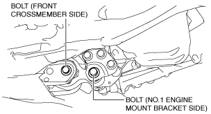
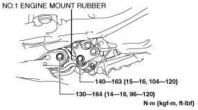
11. Tighten the No.1 engine mount rubber installation bolts shown in the figure.
am3uuw00011892
|
Tightening torque
|
Installation position |
Tightening torque |
|---|---|
|
No.1 engine mount bracket side
|
SKYACTIV-G 1.5: 130—142 N·m {13.3—14.4 kgf·m, 96—104 ft·lbf}
SKYACTIV-G 2.0, SKYACTIV-G 2.5: 140—163 N·m {15—16 kgf·m, 104—120 ft·lbf}
|
|
Front crossmember side
|
130—164 N·m {14—16 kgf·m, 96—120 ft·lbf}
|
12. Install the clips shown in the figure. (with i-ELOOP)
am6zzw00010037
|
13. Connect the generator terminal B cable. (with i-ELOOP) (See GENERATOR REMOVAL/INSTALLATION [SKYACTIV-G 1.5, SKYACTIV-G 2.0, SKYACTIV-G 2.5 (WITH i-ELOOP)].)
14. Install the service plug. (with i-ELOOP) (See SERVICE PLUG DISCONNECTION/CONNECTION [i-ELOOP].)
No.1 Engine Mount Type B
ac5wzw00004652
|
|
1
|
Bracket plate
|
|
2
|
No.1 engine mount rubber, front crossmember component
|
|
3
|
No.1 engine mount bracket
|
|
4
|
No.4 engine mount bracket
|
|
5
|
No.3 engine mount
|
|
6
|
Engine, transaxle
|
No.1 engine mount rubber, front crossmember component removal note (No.1 engine mount type B)
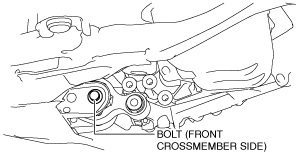
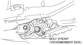
1. Loosen the No.1 engine mount rubber installation bolt (front crossmember side) shown in the figure.
am3uuw00012924
|
2. Remove the No.1 engine mount rubber and the front crossmember component as a single unit. (See FRONT CROSSMEMBER REMOVAL/INSTALLATION [SKYACTIV-G 1.5, SKYACTIV-G 2.0, SKYACTIV-G 2.5].)
No.3 engine mount, No.4 engine mount bracket removal note (No.1 engine mount type B)
1. Secure the engine and transaxle using a commercially available engine lifter.
am3uuw00008802
|
2. Remove the No.4 engine mount bracket.
3. Remove the No.3 engine mount.
Engine mount installation note (No.1 engine mount type B)
1. Tighten the engine front cover stud bolts.
am3uuw00008803
|
2. Tighten the transaxle stud bolts.
ac5uuw00000612
|
3. Secure the engine and transaxle using a commercially available engine lifter.
am3uuw00008802
|
4. Temporarily tighten the No.3 engine mount installation bolts and nuts using the following procedure:
ac5uuw00003037
|
ac5uuw00003038
|
5. Temporarily tighten the No.4 engine mount bracket installation bolt and nuts using the following procedure:
ac5uuw00000615
|
ac5uuw00003039
|
6. Install the No.1 engine mount rubber and the front crossmember component as a single unit. (See FRONT CROSSMEMBER REMOVAL/INSTALLATION [SKYACTIV-G 1.5, SKYACTIV-G 2.0, SKYACTIV-G 2.5].)
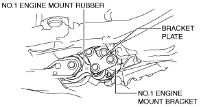
7. Temporarily tighten the No.1 engine mount bracket, No.1 engine mount rubber and bracket plate.
am3uuw00012925
|
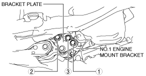
8. Tighten the No.1 engine mount bracket and bracket plate installation bolts in the order shown in the figure.
am3uuw00012926
|
9. Tighten the No.3 engine mount installation bolts and nuts in the order shown in the figure.
am3zzw00014968
|
Tightening torque
|
Installation position |
Tightening torque |
|---|---|
|
1
|
76—95 N·m {7.8—9.6 kgf·m, 57—70 ft·lbf}
|
|
2
|
82—95 N·m {8.4—9.6 kgf·m, 61—70 ft·lbf}
|
|
3
|
49—65 N·m {5.0—6.6 kgf·m, 37—47 ft·lbf}
|
10. Tighten the No.4 engine mount bracket installation bolt and nuts in the order shown in the figure.
am3zzw00014969
|
Tightening torque
|
Installation position |
Tightening torque |
|---|---|
|
1, 2, 3
|
92—116 N·m {9.4—11 kgf·m, 68—85 ft·lbf}
|
|
4
|
81—99 N·m {8.3—10 kgf·m, 60—73 ft·lbf}
|
11. Tighten the No.1 engine mount rubber installation bolts.
am3uuw00012927
|