23
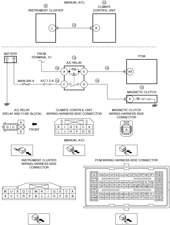
A/C DOES NOT WORK SUFFICIENTLY
DESCRIPTION
• The A/C compressor magnetic clutch does not engage when the A/C is turned on.
POSSIBLE CAUSE
• Improper magnetic clutch clearance
• Refrigerant pressure sensor is stuck open
• Improper refrigerant charge amount
• Evaporator temperature sensor malfunction
• Instrument cluster malfunction (does not transmit A/C request signal to PCM)
• Climate control unit malfunction (A/C switch malfunction or climate control unit does not determine A/C request or transmit the A/C request signal)
• Communication error between instrument cluster and climate control unit (with full-auto air conditioner)
• Communication error between PCM and instrument cluster
• Open or short to power supply circuit between instrument cluster terminal L and climate control unit terminal B (with manual air conditioner)
• Poor ground of A/C magnetic clutch
• Open A/C magnetic clutch
• A/C relay stuck open
• Improper A/C cut-off control
• Open circuit in wiring harness between A/C relay and PCM
• Open circuit in wiring harness between A/C relay and front body control module (FBCM)
• Open circuit in wiring harness between A/C relay and battery
• Open circuit in wiring harness between A/C relay and magnetic clutch
• PCM malfunction