 |
am3zzw00017098
ENGINE REMOVAL/INSTALLATION [SKYACTIV-D 1.5]
id0110q2800400
Operation After Replacing Engine
1. After replacing the engine, perform the following procedure.
|
STEP |
ACTION |
PAGE/CONDITION |
|---|---|---|
|
1
|
Perform KOEO self-test procedure.
|
|
|
2
|
Switch the ignition off.
|
—
|
|
3
|
Verify that the check engine light does not illuminate.
|
—
|
|
4
|
Perform KOER self-test procedure.
|
|
|
5
|
Perform fuel injector injection amount correction.
|
|
|
6
|
Perform timing chain learning procedure.
|
|
|
7
|
Clear the DTCs.
|
|
|
8
|
Switch the ignition off.
|
—
|
Removal/Installation
1. Disconnect the negative battery cable. (See NEGATIVE BATTERY CABLE DISCONNECTION/CONNECTION [SKYACTIV-D 1.5].)
2. Remove the engine cover. (See ENGINE COVER REMOVAL/INSTALLATION [SKYACTIV-D 1.5].)
3. Remove the air cleaner, air hose and fresh-air duct. (See INTAKE-AIR SYSTEM REMOVAL/INSTALLATION [SKYACTIV-D 1.5].)
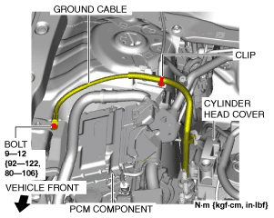
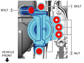
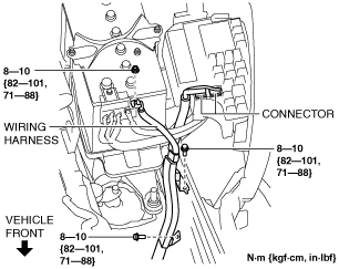
4. Remove the bolts, nut and connector shown in the figure, and set the wiring harness aside.
am3zzw00017098
|
5. Remove the battery and battery tray. (See BATTERY REMOVAL/INSTALLATION [SKYACTIV-D 1.5].)
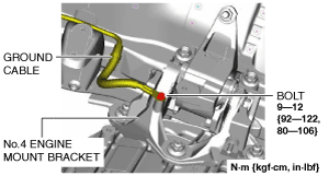
6. Disconnect the ground cable shown in the figure.
Right side
am3zzw00017099
|
Left side
am3zzw00017100
|
7. Remove the air inlet pipe. (See INTAKE-AIR SYSTEM REMOVAL/INSTALLATION [SKYACTIV-D 1.5].)
8. Remove the front under cover No.1 and No.2. (See FRONT UNDER COVER No.1 REMOVAL/INSTALLATION.) (See FRONT UNDER COVER No.2 REMOVAL/INSTALLATION.)
9. Drain the engine coolant and the coolant in the water-cooled charge air cooler. (See ENGINE COOLANT REPLACEMENT [SKYACTIV-D 1.5].) (See WATER-COOLED CHARGE AIR COOLER COOLANT REPLACEMENT [SKYACTIV-D 1.5].)
10. Drain the transaxle oil (MTX) or ATF (ATX). (See MANUAL TRANSAXLE OIL REPLACEMENT [C66M-R].) (See AUTOMATIC TRANSAXLE FLUID (ATF) REPLACEMENT [EW6A-EL].)
11. Remove the insulator. (See EXHAUST SYSTEM REMOVAL/INSTALLATION [SKYACTIV-D 1.5].)
12. Disconnect the selector cable. (ATX) (See AUTOMATIC TRANSAXLE SHIFT MECHANISM REMOVAL/INSTALLATION.)
13. Disconnect the control cable. (MTX) (See MANUAL TRANSAXLE SHIFT MECHANISM REMOVAL/INSTALLATION [C66M-R].)
14. Remove the clutch release cylinder with the pipe still connected. (MTX) (See CLUTCH RELEASE CYLINDER REMOVAL/INSTALLATION [C66M-R].)
15. Disconnect the vacuum hose on the engine side. (See VACUUM HOSE REMOVAL/INSTALLATION.)
16. Disconnect the fuel main hose and fuel return hose No.1 from lower case. (See LOWER CASE REMOVAL/INSTALLATION [SKYACTIV-D 1.5].)
17. Disconnect the upper radiator hose from engine side.
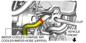
18. Disconnect the water-cooled charge air cooler water hose (upper) from water-cooled charge air cooler reserve tank. (See WATER-COOLED CHARGE AIR COOLER RESERVE TANK REMOVAL/INSTALLATION [SKYACTIV-D 1.5].)
am3zzw00017101
|
19. Disconnect the heater hose from body side. (See A/C UNIT REMOVAL/INSTALLATION.)
20. Remove the front wheels and tires. (See GENERAL PROCEDURES (SUSPENSION).)
21. Remove the front splash shield. (See SPLASH SHIELD REMOVAL/INSTALLATION.)
22. Remove the drive belt. (See DRIVE BELT REMOVAL/INSTALLATION [SKYACTIV-D 1.5].)
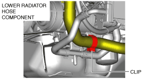
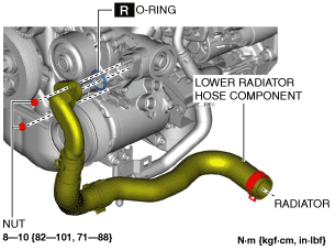
23. Disconnect the clip of the lower radiator hose component.
am3zzw00017102
|
24. Remove the lower radiator hose component.
am3zzw00017103
|
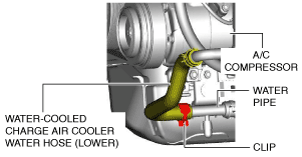
25. Disconnect the water-cooled charge air cooler water hose (lower) from water pipe.
am3zzw00017104
|
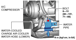
26. Remove the water pipe bolt shown in the figure.
am3zzw00017105
|
27. Remove the A/C compressor with the pipes connected and secure the A/C compressor using wire or rope so that it is out of the way. (See A/C COMPRESSOR REMOVAL/INSTALLATION [SKYACTIV-D 1.5].)
28. Remove the middle pipe installation nut (catalytic converter side) and set the middle pipe out of the way. (See EXHAUST SYSTEM REMOVAL/INSTALLATION [SKYACTIV-D 1.5].)
29. Disconnect the front drive shaft from the transaxle side and set the drive shaft out of the way. (See FRONT DRIVE SHAFT REMOVAL/INSTALLATION.)
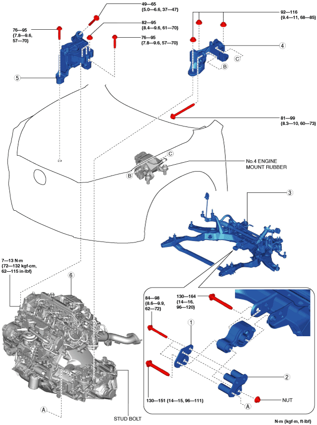
30. Remove in the order indicated in the table.
31. Install in the reverse order of removal.
32. Refill the transaxle oil (MTX) or ATF (ATX). (See MANUAL TRANSAXLE OIL REPLACEMENT [C66M-R].) (See AUTOMATIC TRANSAXLE FLUID (ATF) REPLACEMENT [EW6A-EL].)
33. Refill with engine coolant and water-cooled charge air cooler coolant. (See ENGINE COOLANT REPLACEMENT [SKYACTIV-D 1.5].) (See WATER-COOLED CHARGE AIR COOLER COOLANT REPLACEMENT [SKYACTIV-D 1.5].)
34. If the engine is replaced, perform “Operation After Replacing Engine”. (See Operation After Replacing Engine.)
35. Start the engine, and inspect and adjust the following:
am3zzw00017106
|
|
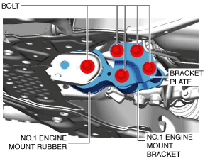
1
|
Bracket plate
|
|
2
|
No.1 engine mount bracket
|
|
3
|
No.1 engine mount rubber, front crossmember component
|
|
4
|
No.4 engine mount bracket
|
|
5
|
No.3 engine mount
|
|
6
|
Engine, transaxle
|
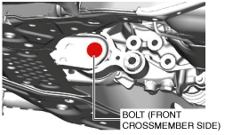
No.1 Engine Mount Rubber, Front Crossmember Component Removal Note
1. Loosen the No.1 engine mount rubber installation bolt (front crossmember side) shown in the figure.
am3zzw00017107
|
2. Remove the No.1 engine mount rubber and the front crossmember component as a single unit. (See FRONT CROSSMEMBER REMOVAL/INSTALLATION [SKYACTIV-D 1.5, SKYACTIV-D 2.2].)
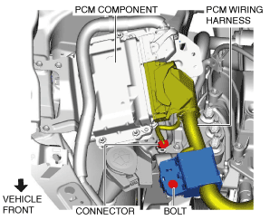
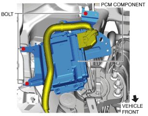
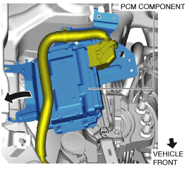
No.3 Engine Mount, No.4 Engine Mount Bracket Removal Note
1. Set the PCM wiring harness and PCM component aside using the following procedure:
am3zzw00017108
|
am3zzw00017109
|
am3zzw00017110
|
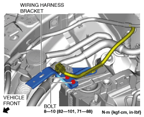
2. Set the wiring harness bracket aside using the following procedure:
am3zzw00017111
|
am3zzw00017112
|
3. Remove the seal plate installed to the underside of the oil pan. (See OIL PAN REMOVAL/INSTALLATION [SKYACTIV-D 1.5].)
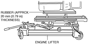
4. Secure the engine and transaxle using a commercially available engine lifter.
ac5wzw00005640
|
5. Remove the No.4 engine mount bracket.
6. Remove the No.3 engine mount.
Engine Mount Installation Note
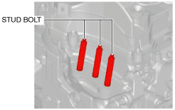
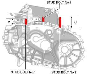
1. Tighten the engine front cover stud bolts.
ac3wzw00001751
|
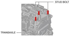
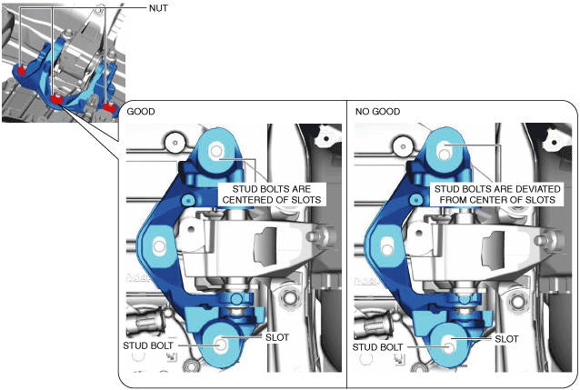
2. Measure the projection of the transaxle stud bolts. (MTX)
ac3wzw00001157
|
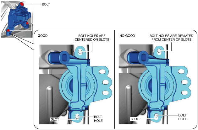
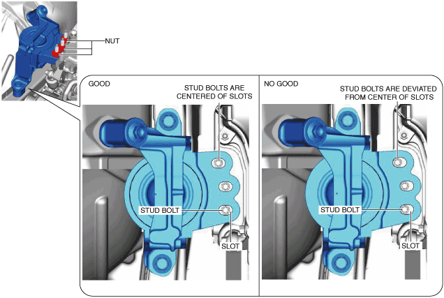
3. Tighten the transaxle stud bolts. (ATX)
ac3wzw00000647
|
4. Secure the engine and transaxle using a commercially available engine lifter.
am2zzw00010107
|
5. Temporarily tighten the No.3 engine mount installation bolts and nuts using the following procedure:
am3zzw00017113
|
am3zzw00017114
|
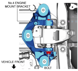
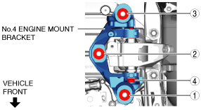
6. Temporarily tighten the No.4 engine mount bracket installation bolt and nuts using the following procedure:
am3zzw00017115
|
am3zzw00017116
|
7. Install the No.1 engine mount rubber and the front crossmember component as a single unit. (See FRONT CROSSMEMBER REMOVAL/INSTALLATION [SKYACTIV-D 1.5, SKYACTIV-D 2.2].)
8. Temporarily tighten the No.1 engine mount bracket, No.1 engine mount rubber and bracket plate.
am3zzw00017117
|
9. Tighten the No.1 engine mount bracket and bracket plate installation bolts in the order shown in the figure.
am3zzw00017118
|
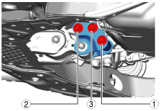
10. Tighten the No.3 engine mount installation bolts and nuts in the order shown in the figure.
am3zzw00017119
|
Tightening torque
|
Installation position |
Tightening torque |
|---|---|
|
1
|
76—95 N·m {7.8—9.6 kgf·m, 57—70 ft·lbf}
|
|
2
|
82—95 N·m {8.4—9.6 kgf·m, 61—70 ft·lbf}
|
|
3
|
49—65 N·m {5.0—6.6 kgf·m, 37—47 ft·lbf}
|
11. Tighten the No.4 engine mount bracket installation bolt and nuts in the order shown in the figure.
am3zzw00017120
|
Tightening torque
|
Installation position |
Tightening torque |
|---|---|
|
1, 2, 3
|
92—116 N·m {9.4—11 kgf·m, 68—85 ft·lbf}
|
|
4
|
81—99 N·m {8.3—10 kgf·m, 60—73 ft·lbf}
|
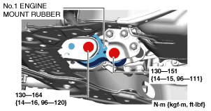
12. Tighten the No.1 engine mount rubber installation bolts.
am3zzw00017121
|
13. Install the seal plate. (See OIL PAN REMOVAL/INSTALLATION [SKYACTIV-D 1.5].)
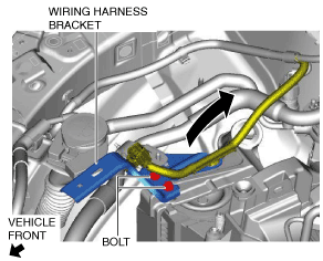
14. Install the wiring harness bracket.
am3zzw00017122
|
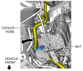
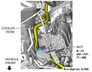
15. Install the cooler hose.
am3zzw00017123
|
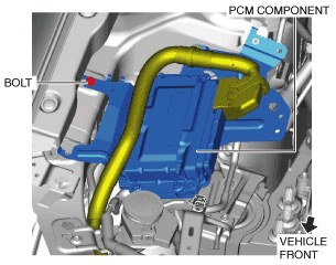
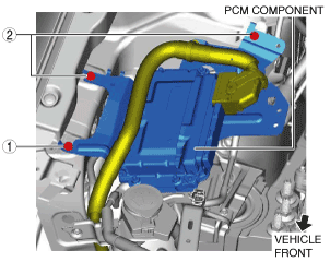
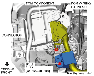
16. Install the PCM component using the following procedure:
am3zzw00017124
|
am3zzw00017125
|
am3zzw00017126
|