 |
ac3wzw00000650
ENGINE DISASSEMBLY/ASSEMBLY [SKYACTIV-D 1.5]
id0110q2800500
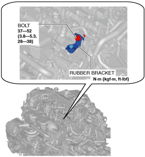
1. Remove the rubber bracket.
ac3wzw00000650
|
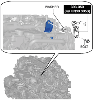
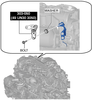
2. Install the SST to the position shown in the figure using the following bolt and washer.
ac3wzw00000651
|
ac3wzw00000652
|
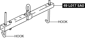
3. Engage the hooks of the SST (49 L017 5A0) to the SST (49 UN30 3050).
ac5wzw00005215
|
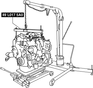
4. To ensure the safety of the work (control engine and transaxle sway), set a hoist as shown in the figure.
ac5jjw00005202
|
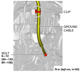
5. Disconnect the ground cable.
ac3wzw00001761
|
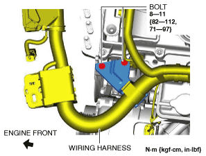
6. Remove the wiring bracket installation bolts.
am3zzw00017127
|
7. Remove the crankshaft pulley cover. (See FRONT OIL SEAL REPLACEMENT [SKYACTIV-D 1.5].)
8. Remove the exhaust system. (See EXHAUST SYSTEM REMOVAL/INSTALLATION [SKYACTIV-D 1.5].)
9. Remove the variable geometry turbocharger. (See TURBOCHARGER WITH VARIABLE TURBINE GEOMETRY REMOVAL/INSTALLATION [SKYACTIV-D 1.5].)
10. Remove the bracket No.1. (See FRONT DRIVE SHAFT REMOVAL/INSTALLATION.)
11. Remove the electric water pump. (See ELECTRIC WATER PUMP REMOVAL/INSTALLATION [SKYACTIV-D 1.5].)
12. Remove the starter. (See STARTER REMOVAL/INSTALLATION [SKYACTIV-D 1.5].)
13. Remove the generator. (See GENERATOR REMOVAL/INSTALLATION [SKYACTIV-D 1.5].)
14. Remove the drive belt auto tensioner. (See DRIVE BELT AUTO TENSIONER REMOVAL/INSTALLATION [SKYACTIV-D 1.5].)
15. Lock the drive plate against rotation using the crankshaft pulley lock bolt. (ATX)
16. Remove the torque converter installation nut from the starter installation hole. (See AUTOMATIC TRANSAXLE REMOVAL/INSTALLATION [EW6A-EL].)
17. Disconnect the engine and transaxle, and lower only the engine from the engine lifter. (See MANUAL TRANSAXLE REMOVAL/INSTALLATION [C66M-R (SKYACTIV-D 1.5)] (MTX).) (See AUTOMATIC TRANSAXLE REMOVAL/INSTALLATION [EW6A-EL] (ATX).)
18. Remove the clutch cover and clutch disc. (MTX) (See CLUTCH UNIT REMOVAL/INSTALLATION [C66M-R].)
19. Remove the water-cooled charge air cooler reserve tank. (See WATER-COOLED CHARGE AIR COOLER RESERVE TANK REMOVAL/INSTALLATION [SKYACTIV-D 1.5].)
20. Remove the intake-air system. (See INTAKE-AIR SYSTEM REMOVAL/INSTALLATION [SKYACTIV-D 1.5].)
21. Remove the following fuel system related parts:
22. Remove the glow plugs. (See GLOW PLUG REMOVAL/INSTALLATION [SKYACTIV-D 1.5].)
23. Remove the vacuum pump. (See VACUUM PUMP REMOVAL/INSTALLATION [SKYACTIV-D 1.5].)
24. Remove the oil cooler. (See OIL COOLER REMOVAL/INSTALLATION [SKYACTIV-D 1.5].)
25. Remove the oil filter. (See OIL FILTER REPLACEMENT [SKYACTIV-D 1.5].)
26. Remove the engine oil solenoid valve. (See ENGINE OIL SOLENOID VALVE REMOVAL/INSTALLATION [SKYACTIV-D 1.5].)
27. Remove the following control system related parts:
28. Remove in the order indicated in the table.
29. Assemble in the reverse order of disassembly.
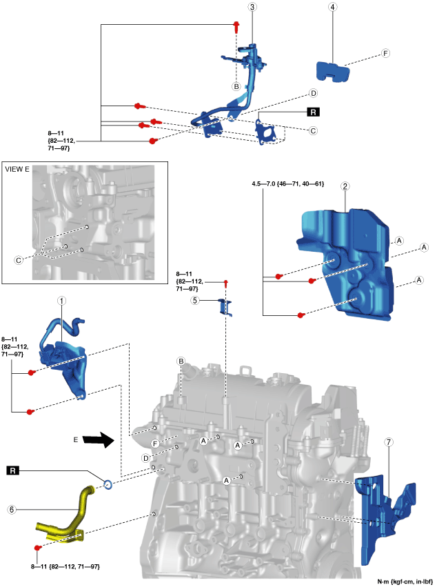
Step 1
ac3wzw00001762
|
|
1
|
Turbocharger solenoid valve component
|
|
2
|
Insulator No.1
|
|
3
|
Exhaust gas pressure sensor No.1 component
|
|
4
|
Insulator No.2
|
|
5
|
Exhaust gas temperature sensor No.2 bracket
|
|
6
|
Water pipe
(See Water pipe installation note.)
|
|
7
|
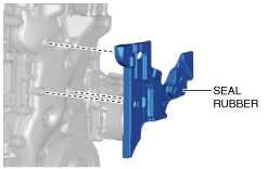
Seal rubber
(See Seal rubber removal note.)
|
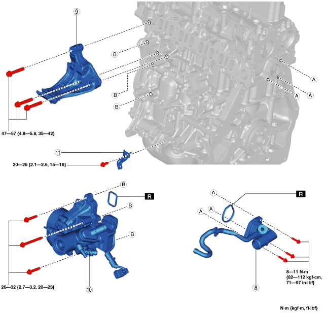
Step 2
ac3wzw00001763
|
|
8
|
Water outlet
|
|
9
|
Generator bracket
|
|
10
|
Water pump component
|
|
11
|
Electric water pump bracket
|
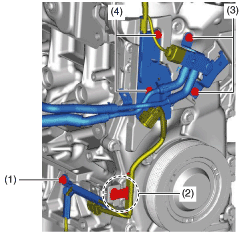
Seal rubber removal note
1. Disconnect or remove the following parts in the order of the numbers shown in the figure.
am3zzw00017128
|
2. Remove the engine wiring harness.
3. Remove the seal rubber.
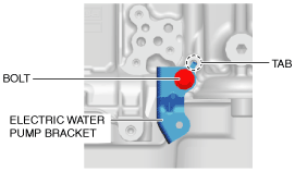
Electric water pump bracket installation note
1. Insert the tab of the electric water pump bracket into the lower cylinder block hole and install the electric water pump bracket.
ac3wzw00001765
|
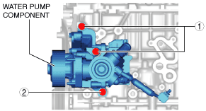
Water pump component installation note
1. Insert a new water pump gasket into the groove of the water pump component.
2. Tighten the water pump component installation bolts in the order shown in the figure.
ac3wzw00001766
|
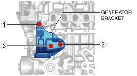
Generator bracket installation note
1. Tighten the generator bracket installation bolt using the following procedure:
ac3wzw00001767
|
Water outlet installation note
Seal rubber installation note
1. Install the seal rubber to the engine.
ac3wzw00001768
|
2. Return the engine wiring harness to its original position.
3. Install the following parts in the order of the numbers shown in the figure.
am3zzw00017129
|
Water pipe installation note
1. Apply engine coolant to the new O-ring.
2. Install the water pipe.